Example for Configuring Frame DM for a PW
This section provides an example for configuring frame delay measurement (DM) for a pseudo wire (PW).
Networking Requirements
As a connection-oriented packet switching technology, Multiprotocol Label Switching Transport Profile (MPLS-TP) is designed to convert a circuit switched transport network to a packet switched transport network. The purpose is to increase the transmission rate on the transport network.
Link reliability must be ensured when MPLS-TP is used. Voice services are used as an example. The coding and decoding of voice packets plus the transmission delay make the delay in VoIP transmission much longer than that in common circuit switched voice transmission. If the delay is longer than 400 ms, the voice quality is affected. If the delay is longer than 2 seconds, VoIP services are unavailable. In addition, if the delay variation (jitter) is longer than the transmission duration of a voice packet, voice quality will drop greatly.
Frame DM can be used to collect delay and jitter statistics and evaluate link performance. DM is a performance monitoring function provided by MPLS-TP and is classified as one-way frame DM or two-way frame DM.

The configuration of two-way frame DM is used as an example in this section. Regardless of one-way or two-way, DM configurations on LSRs are the same except the statistics display configurations.
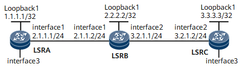
- LSRA and LSRC serve as MEPs.
- LSRB serves as a MIP.
Interfaces 1 through 2 in this example are GE 0/1/0 and GE 0/1/8, respectively.
Device |
Interface |
IP Address |
|---|---|---|
LSRA |
Loopback1 |
1.1.1.1/32 |
GigabitEthernet0/1/0 |
2.1.1.1/24 |
|
LSRB |
Loopback1 |
2.2.2.2/32 |
GigabitEthernet0/1/0 |
2.1.1.2/24 |
|
GigabitEthernet0/1/8 |
3.2.1.1/24 |
|
LSRC |
Loopback1 |
3.3.3.3/32 |
GigabitEthernet0/1/8 |
3.2.1.2/24 |
Configuration Roadmap
The configuration roadmap is as follows:
Create an ME instance and bind it to a PW.
Enable continuity check (CC) and connectivity verification (CV) on the MEP and its remote MEP (RMEP).
Enable two-way frame DM.
Data Preparation
To complete the configuration, you need the following data:
MEG name
ID of the virtual circuit (VC) bound to the ME
Procedure
- Configure a PW over a bidirectional LSP.
For configuration details, see "Configuration Examples" in HUAWEI NetEngine 8000 F SeriesRouter Configuration Guide - VPN or "Configuration Files" in this section.
- Create an ME instance and bind it to the PW.# Create an ME instance named test on LSRA and bind it to the PW.
[~LSRA] mpls-tp meg test
[*LSRA-mpls-tp-meg-test] me l2vc peer-ip 3.3.3.3 vc-id 30000 vc-type vlan mep-id 1 remote-mep-id 2
# Create an ME instance named test on LSRC and bind it to the PW.[~LSRC] mpls-tp meg test [*LSRC-mpls-tp-meg-test] me l2vc peer-ip 1.1.1.1 vc-id 30000 vc-type vlan mep-id 2 remote-mep-id 1
- Enable CC and CV on the MEP and RMEP.# Enable CC and CV on LSRA.
[~LSRA-mpls-tp-meg-test] cc send enable
[~LSRA-mpls-tp-meg-test] cc receive enable
# Enable CC and CV on LSRC.[~LSRC-mpls-tp-meg-test] cc send enable [~LSRC-mpls-tp-meg-test] cc receive enable
- Enable two-way frame DM.
[~LSRA-mpls-tp-meg-test] delay-measure two-way
Two-way delay measure statistics
delay(us):        delay variation(us):
100               --
100               0
100               0
99                1
100               1
The Max delay:100, The Max delay variation:1
The Min delay:99, The Min delay variation:0
The delay average:100, The delay variation average:1
Total sent Packets Number:5, Total received Packets Number: 5
Configuration Files
LSRA configuration file
#
 sysname LSRA
#
 mpls lsr-id 1.1.1.1
 mpls
  mpls te
#
 mpls l2vpn
#
 bidirectional static-cr-lsp ingress Tunnel10
  forward nexthop 2.1.1.2 out-label 20
  backward in-label 20
#
pw-template tpatoc
 peer-address 3.3.3.3
 control-word
 tnl-policy tpatoc
#
interface GigabitEthernet0/1/0
 undo shutdown
 ip address 2.1.1.1 255.255.255.0
 mpls
 mpls te
#
interface GigabitEthernet0/1/0.1
 vlan-type dot1q 1
 mpls
 mpls static-l2vc pw-template tpatoc 30000 transmit-vpn-label 101 receive-vpn-label 101
#
interface LoopBack1
 ip address 1.1.1.1 255.255.255.255
#
interface Tunnel10
 ip address unnumbered interface LoopBack1
 tunnel-protocol mpls te
 destination 2.2.2.2
 mpls te signal-protocol cr-static
 mpls te tunnel-id 100
 mpls te bidirectional
 mpls te reserved-for-binding
#
 ip route-static 2.2.2.2 255.255.255.255 2.1.1.2
 ip route-static 3.3.3.3 255.255.255.255 2.1.1.2
#
tunnel-policy tpatoc
 tunnel binding destination 2.2.2.2 te Tunnel10
#
 mpls-tp meg test
  me l2vc peer-ip 3.3.3.3 vc-id 30000 vc-type vlan mep-id 1 remote-mep-id 2
  cc send enable
  cc receive enable
#
return
LSRB configuration file
#
 sysname LSRB
#
 mpls lsr-id 2.2.2.2
 mpls
  mpls te
#
 bidirectional static-cr-lsp transit lsp1
  forward in-label 20 nexthop 3.2.1.2 out-label 40
  backward in-label 16 nexthop 2.1.1.1 out-label 20
#
interface GigabitEthernet0/1/0
 undo shutdown
 ip address 2.1.1.2 255.255.255.0
 mpls
 mpls te
 ais enable
#
interface GigabitEthernet0/1/8
 undo shutdown
 ip address 3.2.1.1 255.255.255.0
 mpls
 mpls te
 ais enable
#
interface LoopBack1
 ip address 2.2.2.2 255.255.255.255
#
 ip route-static 1.1.1.1 255.255.255.255 2.1.1.1
 ip route-static 3.3.3.3 255.255.255.255 3.2.1.2
#
return
LSRC configuration file
#
 sysname LSRC
#
 mpls lsr-id 3.3.3.3
 mpls
  mpls te
#
 mpls l2vpn
#
 bidirectional static-cr-lsp egress lsp1
  forward in-label 40 lsrid 1.1.1.1 tunnel-id 100
  backward nexthop 3.2.1.1 out-label 16
#
pw-template tpctoa
 peer-address 1.1.1.1
 control-word
 tnl-policy tpctoa
#
interface GigabitEthernet0/1/0
 undo shutdown
 ip address 3.2.1.2 255.255.255.0
 mpls
 mpls te

#
interface GigabitEthernet0/1/0.1
 vlan-type dot1q 1
 mpls static-l2vc pw-template tpctoa 30000 transmit-vpn-label 101 receive-vpn-label 101
#
interface LoopBack1
 ip address 3.3.3.3 255.255.255.255
#
interface Tunnel20
 ip address unnumbered interface LoopBack1
 tunnel-protocol mpls te
 destination 1.1.1.1
 mpls te signal-protocol cr-static
 mpls te tunnel-id 200
 mpls te passive-tunnel
 mpls te binding bidirectional static-cr-lsp egress lsp1
 mpls te reserved-for-binding
#
 ip route-static 1.1.1.1 255.255.255.255 3.2.1.1
 ip route-static 2.2.2.2 255.255.255.255 3.2.1.1
#
tunnel-policy tpctoa
 tunnel binding destination 1.1.1.1 te Tunnel10
#
 mpls-tp meg test
  me l2vc peer-ip 1.1.1.1 vc-id 30000 vc-type vlan mep-id 2 remote-mep-id 1
  cc send enable
  cc receive enable
#
return