Example for Configuring Basic MSTP Functions
This example shows how to configure basic MSTP functions.
Networking Requirements
On a complex network, loops are inevitable. With the requirement for network redundancy backup, network designers tend to deploy multiple physical links between two devices, one of which is the master and the others are the backup. Loops are likely or bound to occur in such a situation. Loops will cause broadcast storms, thereby exhausting network resources and paralyzing the network. Loops also cause flapping of MAC address tables and thus damages MAC address entries. MSTP can be deployed to eliminate loops. MSTP blocks redundant links on a Layer 2 network and trims the network into a loop-free tree.
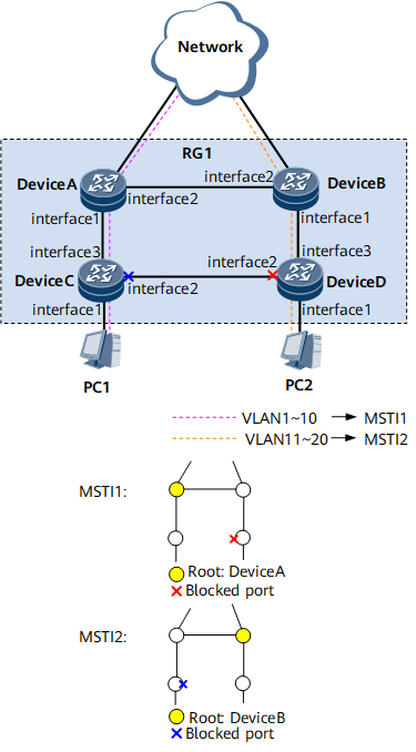
As shown in Figure 1, to load balance traffic of VLANs 1 to 10 and traffic of VLANs 11 to 20, multiple MSTIs are created. MSTP defines a VLAN mapping table in which VLANs are associated with spanning tree instances. In addition, MSTP divides a switching network into multiple regions, each of which has multiple independent spanning tree instances.
As shown in Figure 1, DeviceA, DeviceB, DeviceC, and DeviceD all run MSTP.
Configuration Roadmap
The configuration roadmap is as follows:
- Configure basic MSTP functions:
Configure an MST region and create multiple MSTIs to implement load balancing.
In the MST region, configure a primary root bridge and secondary root bridge for each MSTI.
Set path costs for ports to be blocked in each MSTI.
- Enable MSTP to eliminate loops, including:
Enable MSTP globally.
Enable MSTP on all the interfaces except the interfaces connected to terminals.

MSTP is not required on the interfaces connected to terminals because these interfaces do not need to participate in MSTP calculation.
By default, MSTP is enabled on a Layer 2 interface.
Configure MSTP protection functions, for example, configure root protection on a designated port of a root bridge in each MSTI.
Configure the Layer 2 forwarding function on devices.
Data Preparation
To complete the configuration, you need the following data:
Region name RG1
MSTIs, MSTI 1 and MSTI 2
GE interface numbers
Primary and secondary root bridges of MSTI 1 (DeviceA and DeviceB respectively) and primary and secondary root bridges of MSTI 2 (DeviceB and DeviceA respectively)
Path costs of the ports to be blocked (20000)
VLAN IDs (1 to 20)
VLAN to which PC1 belongs (VLAN 10) and VLAN to which PC2 belongs (VLAN 20)
Procedure
- Configure basic MSTP functions.
Add DeviceA, DeviceB, DeviceC, and DeviceD to MST region RG1, and create two MSTIs, MSTI 1 and MSTI 2.
# Add DeviceA to RG1.
<HUAWEI> system-view
[~HUAWEI] sysname DeviceA
[*HUAWEI] commit
[~DeviceA] stp region-configuration
[~DeviceA-mst-region] region-name RG1
[*DeviceA-mst-region] instance 1 vlan 1 to 10
[*DeviceA-mst-region] instance 2 vlan 11 to 20
[*DeviceA-mst-region] commit
[~DeviceA-mst-region] quit
# Add DeviceB to RG1.
<HUAWEI> system-view
[~HUAWEI] sysname DeviceB
[*HUAWEI] commit
[~DeviceB] stp region-configuration
[~DeviceB-mst-region] region-name RG1
[*DeviceB-mst-region] instance 1 vlan 1 to 10
[*DeviceB-mst-region] instance 2 vlan 11 to 20
[*DeviceB-mst-region] commit
[~DeviceB-mst-region] quit
# Add DeviceC to RG1.
<HUAWEI> system-view
[~HUAWEI] sysname DeviceC
[*HUAWEI] commit
[~DeviceC] stp region-configuration
[~DeviceC-mst-region] region-name RG1
[*DeviceC-mst-region] instance 1 vlan 1 to 10
[*DeviceC-mst-region] instance 2 vlan 11 to 20
[*DeviceC-mst-region] commit
[~DeviceC-mst-region] quit
# Add DeviceD to RG1.
<HUAWEI> system-view
[~HUAWEI] sysname DeviceD
[*HUAWEI] commit
[~DeviceD] stp region-configuration
[~DeviceD-mst-region] region-name RG1
[*DeviceD-mst-region] instance 1 vlan 1 to 10
[*DeviceD-mst-region] instance 2 vlan 11 to 20
[*DeviceD-mst-region] commit
[~DeviceD-mst-region] quit
In RG1, configure primary and secondary root bridges for MSTI 1 and MSTI 2.
Configure primary and secondary root bridges for MSTI 1.
# Configure DeviceA as a primary root bridge of MSTI 1.
[~DeviceA] stp instance 1 root primary
[*DeviceA] commit
# Configure DeviceB as a secondary root bridge of MSTI 1.
[~DeviceB] stp instance 1 root secondary
[*DeviceB] commit
Configure primary and secondary root bridges for MSTI 2.
# Configure DeviceB as a primary root bridge of MSTI 2.
[~DeviceB] stp instance 2 root primary
[*DeviceB] commit
# Configure DeviceA as a secondary root bridge of MSTI 2.
[~DeviceA] stp instance 2 root secondary
[*DeviceA] commit
Set the path costs of the ports to be blocked in MSTI 1 and MSTI 2 to be larger than the default value.
Different calculation methods define different path costs. Use the Huawei proprietary calculation method as an example to set the path costs of the ports to be blocked in MSTI 1 and MSTI 2 to 20000.
All devices on a network must use the same calculation for path costs.
# On DeviceA, configure the path cost calculation method as the Huawei proprietary method.
[~DeviceA] stp pathcost-standard legacy
[*DeviceA] commit
# On DeviceB, configure the path cost calculation method as the Huawei proprietary method.
[~DeviceB] stp pathcost-standard legacy
[*DeviceB] commit
# On DeviceC, configure the path cost calculation method as the Huawei proprietary method and set the path cost of GE 0/1/2 in MSTI 2 to 20000.
[~DeviceC] stp pathcost-standard legacy
[*DeviceC] interface gigabitethernet 0/1/2
[*DeviceC-GigabitEthernet0/1/2] undo shutdown
[*DeviceC-GigabitEthernet0/1/2] portswitch
[*DeviceC-GigabitEthernet0/1/2] stp instance 2 cost 20000
[*DeviceC-GigabitEthernet0/1/2] commit
[~DeviceC-GigabitEthernet0/1/2] quit
# On DeviceD, configure the path cost calculation method as the Huawei proprietary method and set the path cost of GE 0/1/2 in MSTI 1 to 20000.
[~DeviceD] stp pathcost-standard legacy
[*DeviceD] interface gigabitethernet 0/1/2
[*DeviceD-GigabitEthernet0/1/2] stp instance 1 cost 20000
[*DeviceD-GigabitEthernet0/1/2] commit
[~DeviceD-GigabitEthernet0/1/2] quit
Enable MSTP to eliminate loops.
Disable MSTP on interfaces connected to PCs.
# Disable MSTP on GE 0/1/1 of DeviceC.
[~DeviceC] interface gigabitethernet 0/1/1
[*DeviceC-GigabitEthernet0/1/1] undo shutdown
[*DeviceC-GigabitEthernet0/1/1] portswitch
[~DeviceC-GigabitEthernet0/1/1] stp disable
[*DeviceC-GigabitEthernet0/1/1] commit
[~DeviceC-GigabitEthernet0/1/1] quit
# Disable MSTP on GE 0/1/1 of DeviceD.
[~DeviceD] interface gigabitethernet 0/1/1
[*DeviceD-GigabitEthernet0/1/1] undo shutdown
[*DeviceD-GigabitEthernet0/1/1] portswitch
[*DeviceD-GigabitEthernet0/1/1] stp disable
[*DeviceD-GigabitEthernet0/1/1] commit
[~DeviceD-GigabitEthernet0/1/1] quit
Enable MSTP globally.
# Enable MSTP on DeviceA.
[~DeviceA] stp enable
[*DeviceA] commit
# Enable MSTP on DeviceB.
[~DeviceB] stp enable
[*DeviceB] commit
# Enable MSTP on DeviceC.
[~DeviceC] stp enable
[*DeviceC] commit
# Enable MSTP on DeviceD.
[~DeviceD] stp enable
[*DeviceD] commit
Enable MSTP on all the interfaces except the interfaces connected to terminals.
# Enable MSTP on GE 0/1/1 of DeviceA.
[~DeviceA] interface gigabitethernet 0/1/1
[~DeviceA-GigabitEthernet0/1/1] undo shutdown
[*DeviceA-GigabitEthernet0/1/1] portswitch
[*DeviceA-GigabitEthernet0/1/1] stp enable
[*DeviceA-GigabitEthernet0/1/1] commit
[~DeviceA-GigabitEthernet0/1/1] quit
# Enable MSTP on GE 0/1/2 of DeviceA.
[~DeviceA] interface gigabitethernet 0/1/2
[~DeviceA-GigabitEthernet0/1/2] undo shutdown
[*DeviceA-GigabitEthernet0/1/2] portswitch
[*DeviceA-GigabitEthernet0/1/2] stp enable
[*DeviceA-GigabitEthernet0/1/2] commit
[~DeviceA-GigabitEthernet0/1/2] quit
# Enable MSTP on GE 0/1/1 of DeviceB.
[~DeviceB] interface gigabitethernet 0/1/1
[~DeviceB-GigabitEthernet0/1/1] undo shutdown
[*DeviceB-GigabitEthernet0/1/1] portswitch
[*DeviceB-GigabitEthernet0/1/1] stp enable
[*DeviceB-GigabitEthernet0/1/1] commit
[~DeviceB-GigabitEthernet0/1/1] quit
# Enable MSTP on GE 0/1/2 of DeviceB.
[~DeviceB] interface gigabitethernet 0/1/2
[~DeviceB-GigabitEthernet0/1/2] undo shutdown
[*DeviceB-GigabitEthernet0/1/2] portswitch
[*DeviceB-GigabitEthernet0/1/2] stp enable
[*DeviceB-GigabitEthernet0/1/2] commit
[~DeviceB-GigabitEthernet0/1/2] quit
# Enable MSTP on GE 0/1/2 of DeviceC.
[~DeviceC] interface gigabitethernet 0/1/2
[*DeviceC-GigabitEthernet0/1/2] stp enable
[*DeviceC-GigabitEthernet0/1/2] commit
[~DeviceC-GigabitEthernet0/1/2] quit
# Enable MSTP on GE 0/1/3 of DeviceC.
[~DeviceC] interface gigabitethernet 0/1/3
[~DeviceC-GigabitEthernet0/1/3] undo shutdown
[*DeviceC-GigabitEthernet0/1/3] portswitch
[*DeviceC-GigabitEthernet0/1/3] stp enable
[*DeviceC-GigabitEthernet0/1/3] commit
[~DeviceC-GigabitEthernet0/1/3] quit
# Enable MSTP on GE 0/1/2 of DeviceD.
[~DeviceD] interface gigabitethernet 0/1/2
[*DeviceD-GigabitEthernet0/1/2] stp enable
[*DeviceD-GigabitEthernet0/1/2] commit
[~DeviceD-GigabitEthernet0/1/2] quit
# Enable MSTP on GE 0/1/3 of DeviceD.
[~DeviceD] interface gigabitethernet 0/1/3
[~DeviceD-GigabitEthernet0/1/3] undo shutdown
[*DeviceD-GigabitEthernet0/1/3] portswitch
[*DeviceD-GigabitEthernet0/1/3] stp enable
[*DeviceD-GigabitEthernet0/1/3] commit
[~DeviceD-GigabitEthernet0/1/3] quit
- Configure MSTP protection functions, for example, configure root protection on a designated port of a root bridge in each MSTI.
# Enable root protection on GE 0/1/1 of DeviceA.
[~DeviceA] interface gigabitethernet 0/1/1
[~DeviceA-GigabitEthernet0/1/1] stp root-protection
[*DeviceA-GigabitEthernet0/1/1] commit
[~DeviceA-GigabitEthernet0/1/1] quit
# Enable root protection on GE 0/1/1 of DeviceB.
[~DeviceB] interface gigabitethernet 0/1/1
[~DeviceB-GigabitEthernet0/1/1] stp root-protection
[*DeviceB-GigabitEthernet0/1/1] commit
[~DeviceB-GigabitEthernet0/1/1] quit
- Configure the Layer 2 forwarding function on devices in the ring.
Create VLANs 1 to 20 on DeviceA, DeviceB, DeviceC, and DeviceD.
# Create VLANs 1 to 20 on DeviceA.
[~DeviceA] vlan batch 1 to 20
[*DeviceA] commit
# Create VLANs 1 to 20 on DeviceB.
[~DeviceB] vlan batch 1 to 20
[*DeviceB] commit
# Create VLANs 1 to 20 on DeviceC.
[~DeviceC] vlan batch 1 to 20
[*DeviceC] commit
# Create VLANs 1 to 20 on DeviceD.
[~DeviceD] vlan batch 1 to 20
[*DeviceD] commit
Add interfaces on the devices in the ring to VLANs.
# Add GE 0/1/1 on DeviceA to VLANs.
[~DeviceA] interface gigabitethernet 0/1/1
[~DeviceA-GigabitEthernet0/1/1] port trunk allow-pass vlan 1 to 20
[*DeviceA-GigabitEthernet0/1/1] commit
[~DeviceA-GigabitEthernet0/1/1] quit
# Add GE 0/1/2 on DeviceA to VLANs.
[~DeviceA] interface gigabitethernet 0/1/2
[~DeviceA-GigabitEthernet0/1/2] port trunk allow-pass vlan 1 to 20
[*DeviceA-GigabitEthernet0/1/2] commit
[~DeviceA-GigabitEthernet0/1/2] quit
# Add GE 0/1/1 on DeviceB to VLANs.
[~DeviceB] interface gigabitethernet 0/1/1
[~DeviceB-GigabitEthernet0/1/1] port trunk allow-pass vlan 1 to 20
[*DeviceB-GigabitEthernet0/1/1] commit
[~DeviceB-GigabitEthernet0/1/1] quit
# Add GE 0/1/2 on DeviceB to VLANs.
[~DeviceB] interface gigabitethernet 0/1/2
[~DeviceB-GigabitEthernet0/1/2] port trunk allow-pass vlan 1 to 20
[*DeviceB-GigabitEthernet0/1/2] commit
[~DeviceB-GigabitEthernet0/1/2] quit
# Add GE 0/1/2 on DeviceC to VLANs.
[~DeviceC] interface gigabitethernet 0/1/2
[~DeviceC-GigabitEthernet0/1/2] port trunk allow-pass vlan 1 to 20
[*DeviceC-GigabitEthernet0/1/2] commit
[~DeviceC-GigabitEthernet0/1/2] quit
# Add GE 0/1/3 on DeviceC to VLANs.
[~DeviceC] interface gigabitethernet 0/1/3
[~DeviceC-GigabitEthernet0/1/3] port trunk allow-pass vlan 1 to 20
[*DeviceC-GigabitEthernet0/1/3] commit
[~DeviceC-GigabitEthernet0/1/3] quit
# Add GE 0/1/2 on DeviceD to VLANs.
[~DeviceD] interface gigabitEthernet 0/1/2
[~DeviceD-GigabitEthernet0/1/2] port trunk allow-pass vlan 1 to 20
[*DeviceD-GigabitEthernet0/1/2] commit
[~DeviceD-GigabitEthernet0/1/2] quit
# Add GE 0/1/3 on DeviceD to VLANs.
[~DeviceD] interface gigabitethernet 0/1/3
[~DeviceD-GigabitEthernet0/1/3] port trunk allow-pass vlan 1 to 20
[*DeviceD-GigabitEthernet0/1/3] commit
[~DeviceD-GigabitEthernet0/1/3] quit
- Verify the configuration.
After completing the previous configurations, run the following commands to verify the configurations.
# Run the display stp brief command on DeviceA to view the interface status and protection type. The displayed information is as follows:
[~DeviceA] display stp brief
 MSTID      Port                  Role  STP State     Protection
   0        GigabitEthernet0/1/1  DESI  FORWARDING    NONE
   0        GigabitEthernet0/1/2  DESI  FORWARDING    NONE
   1        GigabitEthernet0/1/1  DESI  FORWARDING    NONE
   1        GigabitEthernet0/1/2  DESI  FORWARDING    NONE
   2        GigabitEthernet0/1/1  DESI  FORWARDING    NONE
   2        GigabitEthernet0/1/2  ROOT  FORWARDING    NONE
In MSTI 1, DeviceA is a root bridge and thus GE 0/1/2 and GE 0/1/1 on DeviceA are designated ports. In MSTI 2, GE 0/1/1 on DeviceA is a designated port and GE 0/1/2 is a root port.
# Run the display stp brief command on DeviceB. The displayed information is as follows:
[~DeviceB] display stp brief
 MSTID      Port                  Role  STP State       Protection
   0        GigabitEthernet0/1/1  DESI  FORWARDING      NONE
   0        GigabitEthernet0/1/2  ROOT  FORWARDING      NONE
   1        GigabitEthernet0/1/1  DESI  FORWARDING      NONE
   1        GigabitEthernet0/1/2  ROOT  FORWARDING      NONE
   2        GigabitEthernet0/1/1  DESI  FORWARDING      NONE
   2        GigabitEthernet0/1/2  DESI  FORWARDING      NONE
In MSTI 2, DeviceB is a root bridge and thus GE 0/1/1 and GE 0/1/2 on DeviceB are designated ports. In MSTI 1, GE 0/1/1 of DeviceB is a designated port and GE 0/1/2 is a root port.
# Run the display stp interface brief command on DeviceC. The displayed information is as follows:
[~DeviceC] display stp interface gigabitethernet 0/1/3 brief
 MSTID      Port                    Role  STP State       Protection
   0        GigabitEthernet0/1/3    ROOT  FORWARDING      NONE
   1        GigabitEthernet0/1/3    ROOT  FORWARDING      NONE
   2        GigabitEthernet0/1/3    ROOT  FORWARDING      NONE
[~DeviceC] display stp interface gigabitethernet 0/1/2 brief
 MSTID      Port                    Role  STP State       Protection
   0        GigabitEthernet0/1/2    DESI  FORWARDING      NONE
   1        GigabitEthernet0/1/2    DESI  FORWARDING      NONE
   2        GigabitEthernet0/1/2    ALTE  DISCARDING      NONE
# Run the display stp interface brief command on DeviceD. The displayed information is as follows:
[~DeviceD] display stp interface gigabitethernet 0/1/3 brief
 MSTID      Port                    Role  STP State       Protection
   0        GigabitEthernet0/1/3    ALTE  DISCARDING      NONE
   1        GigabitEthernet0/1/3    ROOT  FORWARDING      NONE
   2        GigabitEthernet0/1/3    ROOT  FORWARDING      NONE
[~DeviceD] display stp interface gigabitethernet 0/1/2 brief
 MSTID      Port                    Role  STP State       Protection
   0        GigabitEthernet0/1/2    ROOT  FORWARDING      NONE
   1        GigabitEthernet0/1/2    ALTE  DISCARDING      NONE
   2        GigabitEthernet0/1/2    DESI  FORWARDING      NONE
GE 0/1/3 on DeviceD is a root port in both MSTI 1 and MSTI 2. GE 0/1/2 on DeviceD is blocked in MSTI 1 but is calculated to be a designated port in MSTI 2.
Configuration Files
Configuration file of DeviceA
#
 sysname DeviceA
#
 vlan batch 1 to 20
#
 stp instance 1 root primary
 stp instance 2 root secondary
 stp pathcost-standard legacy
 stp enable
#
 stp region-configuration
  region-name RG1
  instance 1 vlan 1 to 10
  instance 2 vlan 11 to 20
#
interface GigabitEthernet0/1/1
 undo shutdown
 portswitch
 port trunk allow-pass vlan 1 to 20
 stp root-protection
#
interface GigabitEthernet0/1/2
 undo shutdown
 portswitch
 port trunk allow-pass vlan 1 to 20
#
return
Configuration file of DeviceB
#
 sysname DeviceB
#
 vlan batch 1 to 20
#
 stp instance 1 root secondary
 stp instance 2 root primary
 stp pathcost-standard legacy
 stp enable
#
 stp region-configuration
  region-name RG1
  instance 1 vlan 1 to 10
  instance 2 vlan 11 to 20
#
interface GigabitEthernet0/1/1
 undo shutdown
 portswitch
 port trunk allow-pass vlan 1 to 20
 stp root-protection
#
interface GigabitEthernet0/1/2
 undo shutdown
 portswitch
 port trunk allow-pass vlan 1 to 20
#
return
Configuration file of DeviceC
#
 sysname DeviceC
#
 vlan batch 1 to 20
#
 stp pathcost-standard legacy
 stp enable
#
 stp region-configuration
  region-name RG1
  instance 1 vlan 1 to 10
  instance 2 vlan 11 to 20
#
interface GigabitEthernet0/1/1
 undo shutdown
 portswitch
 stp disable
#
interface GigabitEthernet0/1/2
 undo shutdown
 portswitch
 port trunk allow-pass vlan 1 to 20
 stp instance 2 cost 20000
#
interface GigabitEthernet0/1/3
 undo shutdown
 portswitch
 port trunk allow-pass vlan 1 to 20
#
return
Configuration file of DeviceD
#
 sysname DeviceD
#
 vlan batch 1 to 20
#
 stp pathcost-standard legacy
 stp enable
#
 stp region-configuration
  region-name RG1
  instance 1 vlan 1 to 10
  instance 2 vlan 11 to 20
#
interface GigabitEthernet0/1/1
 undo shutdown
 portswitch
 stp disable
#
interface GigabitEthernet0/1/2
 undo shutdown
 portswitch
 port trunk allow-pass vlan 1 to 20
 stp instance 1 cost 20000
#
interface GigabitEthernet0/1/3
 undo shutdown
 portswitch
 port trunk allow-pass vlan 1 to 20
#
return