Example for Configuring MSTP Multi-process for Layer 2 Single-Access Rings and Layer 2 Multi-Access Rings
Multiple Spanning Tree Protocol (MSTP) multi-process enables different Layer 2 access rings to carry different services.
Networking Requirements
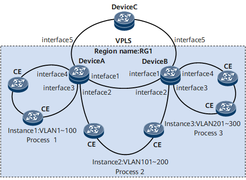
On the networking with both Layer 2 single-access rings and multi-access rings deployed, devices bear both Layer 2 and Layer 3 services. To enable different rings to bear different services, deploy MSTP multi-process. Spanning trees of different processes are calculated independently and do not affect each other.
As shown in Figure 1, both Layer 2 single-access rings and dual-access rings are deployed and DeviceA and DeviceB carry both Layer 2 and Layer 3 services. In this networking, DeviceA and DeviceB connected to dual-access rings are also connected to a single-access ring each.
For detailed configurations of VPLS, see the HUAWEI NetEngine 8000 F Series Configuration Guide - VPN.
Configuration Roadmap
The configuration roadmap is as follows:
Configure basic MSTP functions, add devices to MST regions, and create MSTIs.

Each ring can belong to only one region.
Each CE can join only one ring.
Configure multiple MSTP processes, including:
Create multiple MSTP processes and add interfaces to relevant processes.
Configure a share-link.
Configure MSTP protection functions, including:
Configure priorities of MSTP processes and enable root protection.
Configure share-link protection.
Configure the Layer 2 forwarding function on devices.
Data Preparation
To complete the configuration, you need the following data:
Name of an MST region and names of MSTIs (MSTI 1, MSTI 2, and MSTI 3)
VLAN IDs (1 to 300)
IDs of MSTP processes
Procedure
- Configure basic MSTP functions, add devices to an MST region, and create MSTIs.
Configure an MST region and create MSTIs.
# Configure an MST region and create MSTIs on DeviceA.
<HUAWEI> system-view
[~HUAWEI] sysname DeviceA
[*HUAWEI] commit
[~DeviceA] stp region-configuration
[~DeviceA-mst-region] region-name RG1
[*DeviceA-mst-region] instance 1 vlan 1 to 100
[*DeviceA-mst-region] instance 2 vlan 101 to 200
[*DeviceA-mst-region] instance 3 vlan 201 to 300
[*DeviceA-mst-region] commit
[~DeviceA-mst-region] quit
# Configure an MST region and create MSTIs on DeviceB.
<HUAWEI> system-view
[~HUAWEI] sysname DeviceB
[*HUAWEI] commit
[~DeviceB] stp region-configuration
[~DeviceB-mst-region] region-name RG1
[*DeviceB-mst-region] instance 1 vlan 1 to 100
[*DeviceB-mst-region] instance 2 vlan 101 to 200
[*DeviceB-mst-region] instance 3 vlan 201 to 300
[*DeviceB-mst-region] commit
[~DeviceB-mst-region] quit
Enable MSTP.
# Configure DeviceA.
[~DeviceA] stp enable
[*DeviceA] commit
# Configure DeviceB.
[~DeviceB] stp enable
[*DeviceB] commit
- Configure multiple MSTP processes.
Create multiple MSTP processes and add interfaces to relevant processes.
# Create MSTP processes 1 and 2 on DeviceA.
[~DeviceA] stp process 1
[*DeviceA-mst-process-1] quit
[*DeviceA] stp process 2
[*DeviceA-mst-process-2] commit
[~DeviceA-mst-process-2] quit
# Create MSTP processes 2 and 3 on DeviceB.
[~DeviceB] stp process 2
[*DeviceB-mst-process-2] quit
[*DeviceB] stp process 3
[*DeviceB-mst-process-3] commit
[~DeviceB-mst-process-3] quit
# Add GE 0/1/3 and GE 0/1/4 on DeviceA to MSTP process 1 and GE 0/1/2 to MSTP process 2.
[~DeviceA] interface gigabitethernet 0/1/4
[~DeviceA-GigabitEthernet0/1/4] undo shutdown
[*DeviceA-GigabitEthernet0/1/4] portswitch
[*DeviceA-GigabitEthernet0/1/4] stp enable
[*DeviceA-GigabitEthernet0/1/4] stp binding process 1
[*DeviceA-GigabitEthernet0/1/4] quit
[*DeviceA] interface gigabitethernet 0/1/3
[*DeviceA-GigabitEthernet0/1/3] undo shutdown
[*DeviceA-GigabitEthernet0/1/3] portswitch
[*DeviceA-GigabitEthernet0/1/3] stp enable
[*DeviceA-GigabitEthernet0/1/3] stp binding process 1
[*DeviceA-GigabitEthernet0/1/3] quit
[*DeviceA] interface gigabitethernet 0/1/2
[*DeviceA-GigabitEthernet0/1/2] undo shutdown
[*DeviceA-GigabitEthernet0/1/2] portswitch
[*DeviceA-GigabitEthernet0/1/2] stp enable
[*DeviceA-GigabitEthernet0/1/2] stp binding process 2
[*DeviceA-GigabitEthernet0/1/2] commit
[~DeviceA-GigabitEthernet0/1/2] quit
# Add GE 0/1/3 and GE 0/1/4 on DeviceB to MSTP process 3 and GE 0/1/2 to MSTP process 2.
[~DeviceB] interface gigabitethernet 0/1/4
[~DeviceB-GigabitEthernet0/1/4] undo shutdown
[*DeviceB-GigabitEthernet0/1/4] portswitch
[*DeviceB-GigabitEthernet0/1/4] stp enable
[*DeviceB-GigabitEthernet0/1/4] stp binding process 3
[*DeviceB-GigabitEthernet0/1/4] quit
[*DeviceB] interface gigabitethernet 0/1/3
[*DeviceB-GigabitEthernet0/1/3] undo shutdown
[*DeviceB-GigabitEthernet0/1/3] portswitch
[*DeviceB-GigabitEthernet0/1/3] stp enable
[*DeviceB-GigabitEthernet0/1/3] stp binding process 3
[*DeviceB-GigabitEthernet0/1/3] quit
[*DeviceB] interface gigabitethernet 0/1/2
[*DeviceB-GigabitEthernet0/1/2] undo shutdown
[*DeviceB-GigabitEthernet0/1/2] portswitch
[*DeviceB-GigabitEthernet0/1/2] stp enable
[*DeviceB-GigabitEthernet0/1/2] stp binding process 2
[*DeviceB-GigabitEthernet0/1/2] commit
[~DeviceB-GigabitEthernet0/1/2] quit
Configure a share-link.
# Configure DeviceA.
[~DeviceA] interface gigabitethernet0/1/1
[~DeviceA-GigabitEthernet0/1/1] undo shutdown
[*DeviceA-GigabitEthernet0/1/1] portswitch
[*DeviceA-GigabitEthernet0/1/1] stp enable
[*DeviceA-GigabitEthernet0/1/1] stp binding process 2 link-share
[*DeviceA-GigabitEthernet0/1/1] commit
[~DeviceA-GigabitEthernet0/1/1] quit
# Configure DeviceB.
[~DeviceB] interface gigabitethernet0/1/1
[~DeviceB-GigabitEthernet0/1/1] undo shutdown
[*DeviceB-GigabitEthernet0/1/1] portswitch
[*DeviceB-GigabitEthernet0/1/1] stp enable
[*DeviceB-GigabitEthernet0/1/1] stp binding process 2 link-share
[*DeviceB-GigabitEthernet0/1/1] commit
[~DeviceB-GigabitEthernet0/1/1] quit
Enable the MSTP function in MSTP multi-process.
# Configure DeviceA.
[~DeviceA] stp process 1
[~DeviceA-stp-process-1] stp enable
[*DeviceA-stp-process-1] quit
[*DeviceA] stp process 2
[*DeviceA-stp-process-2] stp enable
[*DeviceA-stp-process-2] commit
[~DeviceA-stp-process-2] quit
# Configure DeviceB.
[~DeviceB] stp process 3
[~DeviceB-stp-process-3] stp enable
[*DeviceB-stp-process-3] quit
[*DeviceB] stp process 2
[*DeviceB-stp-process-2] stp enable
[*DeviceB-stp-process-2] commit
[~DeviceB-stp-process-2] quit
- Configure MSTP protection functions.
Configure priorities of MSTP processes and enable root protection.
# Configure DeviceA.
[~DeviceA] stp process 1
[~DeviceA-stp-process-1] stp instance 0 root primary
[*DeviceA-stp-process-1] stp instance 1 root primary
[*DeviceA-stp-process-1] quit
[*DeviceA] stp process 2
[*DeviceA-stp-process-2] stp instance 0 root primary
[*DeviceA-stp-process-2] stp instance 2 root primary
[*DeviceA-stp-process-2] quit
[*DeviceA] interface gigabitethernet 0/1/2
[*DeviceA-GigabitEthernet0/1/2] stp root-protection
[*DeviceA-GigabitEthernet0/1/2] commit
[~DeviceA-GigabitEthernet0/1/2] quit
# Configure DeviceB.
[~DeviceB] stp process 3
[~DeviceB-stp-process-3] stp instance 0 root primary
[*DeviceB-stp-process-3] stp instance 3 root primary
[*DeviceB-stp-process-3] quit
[*DeviceB] stp process 2
[*DeviceB-stp-process-2] stp instance 0 root secondary
[*DeviceB-stp-process-2] stp instance 2 root secondary
[*DeviceB-stp-process-2] quit
[*DeviceB] interface gigabitethernet 0/1/2
[*DeviceB-GigabitEthernet0/1/2] stp root-protection
[*DeviceB-GigabitEthernet0/1/2] commit
[~DeviceB-GigabitEthernet0/1/2] quit
In each ring, the priority of the MSTP process on the downstream CE must be lower than the priority of the MSTP process on the UPE.
For DeviceA and DeviceB on the dual-access ring, you are recommended to configure them as the primary root bridges of different MSTIs.
Configure share-link protection.
# Configure DeviceA.
[~DeviceA] stp process 2
[~DeviceA-stp-process-2] stp link-share-protection
[*DeviceA-stp-process-2] commit
[~DeviceA-stp-process-2] quit
# Configure DeviceB.
[~DeviceB] stp process 2
[~DeviceB-stp-process-2] stp link-share-protection
[*DeviceB-stp-process-2] commit
[~DeviceB-stp-process-2] quit
- Create VLANs and add interfaces to VLANs.
# Create VLANs 1 to 200 on DeviceA. Add GE 0/1/3 and GE 0/1/4 to VLANs 1 to 100, and add GE 0/1/1 and GE 0/1/2 to VLANs 101 to 200.
[~DeviceA] vlan batch 1 to 200
[*DeviceA] interface gigabitethernet 0/1/3
[*DeviceA-GigabitEthernet0/1/3] port trunk allow-pass vlan 1 to 100
[*DeviceA-GigabitEthernet0/1/3] quit
[*DeviceA] interface gigabitethernet 0/1/4
[*DeviceA-GigabitEthernet0/1/4] port trunk allow-pass vlan 1 to 100
[*DeviceA-GigabitEthernet0/1/4] quit
[*DeviceA] interface gigabitethernet 0/1/1
[*DeviceA-GigabitEthernet0/1/1] port trunk allow-pass vlan 101 to 200
[*DeviceA-GigabitEthernet0/1/1] quit
[*DeviceA] interface gigabitethernet 0/1/2
[*DeviceA-GigabitEthernet0/1/2] port trunk allow-pass vlan 101 to 200
[*DeviceA-GigabitEthernet0/1/2] commit
[~DeviceA-GigabitEthernet0/1/2] quit
# Create VLANs 101 to 300 on DeviceB. Add GE 0/1/3 and GE 0/1/4 to VLANs 201 to 300, and add GE 0/1/1 and GE 0/1/2 to VLANs 101 to 200.
[~DeviceB] vlan batch 101 to 300
[*DeviceB] interface gigabitethernet 0/1/1
[*DeviceB-GigabitEthernet0/1/1] port trunk allow-pass vlan 101 to 200
[*DeviceB-GigabitEthernet0/1/1] quit
[*DeviceB] interface gigabitethernet 0/1/2
[*DeviceB-GigabitEthernet0/1/2] port trunk allow-pass vlan 101 to 200
[*DeviceB-GigabitEthernet0/1/2] quit
[*DeviceB] interface gigabitethernet 0/1/3
[*DeviceB-GigabitEthernet0/1/3] port trunk allow-pass vlan 201 to 300
[*DeviceB-GigabitEthernet0/1/3] quit
[*DeviceB] interface gigabitethernet 0/1/4
[*DeviceB-GigabitEthernet0/1/4] port trunk allow-pass vlan 201 to 300
[*DeviceB-GigabitEthernet0/1/4] commit
[~DeviceB-GigabitEthernet0/1/4] quit
- Verify the configuration.
Run the display stp interface brief command on DeviceA, and you can view the following information:
# GE 0/1/4 is a designated port in the CIST of MSTP process 1 and in MSTI 1.
[~DeviceA] display stp process 1 interface gigabitethernet 0/1/4 brief
 MSTID      Port                          Role  STP State       Protection
   0    GigabitEthernet0/1/4        DESI  FORWARDING      NONE
   1    GigabitEthernet0/1/4        DESI  FORWARDING      NONE
# GE 0/1/2 is a designated port in the CIST of MSTP process 2 and in MSTI 2.
[~DeviceA] display stp process 2 interface gigabitethernet 0/1/2 brief
 MSTID      Port                         Role  STP State       Protection
   0    GigabitEthernet0/1/2        DESI  FORWARDING      ROOT
   2    GigabitEthernet0/1/2        DESI  FORWARDING      ROOT
Run the display stp interface brief command on DeviceB, and you can view the following information:
# GE 0/1/4 is a designated port in the CIST of MSTP process 3 and in MSTI 3.
[~DeviceB] display stp process 3 interface gigabitethernet 0/1/4 brief
 MSTID      Port                          Role  STP State       Protection
   0    GigabitEthernet0/1/4        DESI  FORWARDING      NONE
   3    GigabitEthernet0/1/4        DESI  FORWARDING      NONE
# GE 0/1/2 is a designated port in the CIST of MSTP process 2 and in MSTI 2.
[~DeviceB] display stp process 2 interface giabitethernet 0/1/2 brief
 MSTID      Port                         Role  STP State       Protection
   0    GigabitEthernet0/1/2        DESI  FORWARDING      ROOT
   2    GigabitEthernet0/1/2        DESI  FORWARDING      ROOT
Configuration Files
Only the MSTP-related configuration files are listed.
Configuration file of DeviceA
#
 sysname DeviceA
#
 vlan batch 1 to 200
#
 stp enable
#
 stp region-configuration
  region-name RG1
  instance 1 vlan 1 to 100
  instance 2 vlan 101 to 200
#
stp process 1
 stp instance 0 root primary
 stp instance 1 root primary
 stp enable
stp process 2
 stp instance 0 root primary
 stp instance 2 root primary
 stp link-share-protection
 stp enable
#
interface GigabitEthernet0/1/1
 undo shutdown
 portswitch
 port trunk allow-pass vlan 101 to 200
 stp binding process 2 link-share
#
interface GigabitEthernet0/1/2
 undo shutdown
 portswitch
 port trunk allow-pass vlan 101 to 200
 stp binding process 2
 stp root-protection
#
interface GigabitEthernet0/1/3
 undo shutdown
 portswitch
 port trunk allow-pass vlan 1 to 100
 stp binding process 1
#
interface GigabitEthernet0/1/4
 undo shutdown
 portswitch
 port trunk allow-pass vlan 1 to 100
 stp binding process 1
#
return
Configuration file of DeviceB
#
 sysname DeviceB
#
 vlan batch 1 to 200
#
 stp enable
#
 stp region-configuration
  region-name RG1
  instance 2 vlan 101 to 200
  instance 3 vlan 1 to 100
#
stp process 2
 stp instance 0 root secondary
 stp instance 2 root secondary
 stp link-share-protection
 stp enable
stp process 3
 stp instance 0 root primary
 stp instance 3 root primary
 stp enable
#
interface GigabitEthernet0/1/1
 undo shutdown
 portswitch
 port trunk allow-pass vlan 101 to 200
 stp binding process 2 link-share
#
interface GigabitEthernet0/1/2
 undo shutdown
 portswitch
 port trunk allow-pass vlan 101 to 200
 stp binding process 2
 stp root-protection
#
interface GigabitEthernet0/1/3
 undo shutdown
 portswitch
 port trunk allow-pass vlan 1 to 100
 stp binding process 3
#
interface GigabitEthernet0/1/4
 undo shutdown
 portswitch
 port trunk allow-pass vlan 1 to 100
 stp binding process 3
#
return