Example for Configuring a PIM-SM BSR Administrative Domain
On a PIM-SM network that uses a BootStrap router (BSR) Rendezvous Point (RP), configure a BSR administrative domain to allow Candidate-BootStrap Routers (C-BSRs) to serve groups in a specified group address range.
Networking Requirements
On the ISP network shown in Figure 1, multicast services are deployed. An IGP is configured on the network and runs properly. It is required that hosts on this network receive the VoD service in multicast mode.
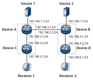
Device |
Interface |
IP Address |
|---|---|---|
Device A |
GE 0/1/0 |
192.168.1.1/24 |
GE 0/1/1 |
192.168.2.1/24 |
|
GE 0/1/2 |
192.168.3.1/24 |
|
Device B |
GE 0/1/0 |
192.168.7.1/24 |
GE 0/1/1 |
192.168.2.2/24 |
|
GE 0/1/2 |
192.168.4.1/24 |
|
Device C |
GE 0/1/2 |
192.168.3.2/24 |
GE 0/1/3 |
192.168.5.1/24 |
|
Device D |
GE 0/1/2 |
192.168.4.2/24 |
GE 0/1/3 |
192.168.6.1/24 |
Precautions
When configuring a PIM-SM BSR administrative domain, note the following precautions:
Unicast routes on the network must be reachable because multicast routing depends on unicast routing.
Multicast routing must be enabled on all routers.
PIM-SM must be enabled on interfaces connecting routers, interfaces directly connecting routers to multicast sources, and interfaces directly connecting routers to hosts.
All routers directly connected to hosts must run the same IGMP version. PIM-SM must be enabled before IGMP is enabled.
Configuration Roadmap
The configuration roadmap is as follows:
Configure an IP address for each router interface and configure a unicast routing protocol.
Enable multicast routing on all multicast routers.
Enable PIM-SM on all router interfaces.
Enable IGMP on router interfaces that directly connect to hosts.
Configure the BSR administrative domain function on all multicast routers.
Configure a C-BSR for a specific multicast group in the BSR administrative domain. Configure one or more routers in a PIM-SM domain as C-RPs to implement dynamic RP election.
Configure a multicast boundary on router interfaces.
Data Preparation
To complete the configuration, you need the following data:
Multicast group address: 239.1.0.0/16 and 239.2.0.0/16
Multicast source address: 192.168.1.2/24 and 192.168.7.2/24
Procedure
- Configure an IP address for each router interface and a unicast routing protocol. For configuration details, see Configuration Files in this section.
- Enable multicast routing on each router and enable PIM-SM on each interface.
# Configure Device A.
[~DeviceA] multicast routing-enable
[*DeviceA] interface gigabitethernet 0/1/0
[*DeviceA-GigabitEthernet0/1/0] pim sm
[*DeviceA-GigabitEthernet0/1/0] quit
[*DeviceA] interface gigabitEthernet 0/1/1
[*DeviceA-GigabitEthernet0/1/1] pim sm
[*DeviceA-GigabitEthernet0/1/1] quit
[*DeviceA] interface gigabitEthernet 0/1/2
[*DeviceA-GigabitEthernet0/1/2] pim sm
[*DeviceA-GigabitEthernet0/1/2] commit
[~DeviceA-GigabitEthernet0/1/2] quit
Repeat this step for Device B, Device C, and Device D. For configuration details, see Configuration Files in this section.
- Enable IGMP on router interfaces that directly connect to hosts. For configuration details, see Configuration Files in this section.
- Configure the BSR administrative domain function on all multicast routers.
[~DeviceA] pim
[*DeviceA-pim] c-bsr admin-scope
[*DeviceA-pim] commit
[~DeviceA-pim] quit
Repeat this step for Device B, Device C, and Device D. For configuration details, see Configuration Files in this section.
- Configure a C-BSR for a specific multicast group in the BSR administrative domain. Configure one or more routers in a PIM-SM domain as C-RPs to implement dynamic RP election.
# Configure router A.
[~DeviceA] pim
[*DeviceA-pim] c-bsr group 239.1.0.0 255.255.0.0
[*DeviceA-pim] c-bsr LoopBack0
[*DeviceA-pim] c-rp LoopBack0
[*DeviceA-pim] commit
[~DeviceA-pim] quit
Repeat this step for Device B. For configuration details, see Configuration Files in this section.
- Configure a multicast boundary on router interfaces.
# Configure Device A.
[~DeviceA] interface gigabitEthernet 0/1/1
[~DeviceA-GigabitEthernet0/1/1] multicast boundary 239.1.0.0 16
[*DeviceA-GigabitEthernet0/1/1] commit
[~DeviceA-GigabitEthernet0/1/1] quit
# Configure Device B.
[~DeviceB] interface gigabitEthernet 0/1/1
[~DeviceB-GigabitEthernet0/1/1] multicast boundary 239.2.0.0 16
[*DeviceB-GigabitEthernet0/1/1] commit
[~DeviceB-GigabitEthernet0/1/1] quit
- Verify the configuration.
# Run the display pim bsr-info command to check BSR information on each router. The following examples use the command outputs on Device A and Device B (C-BSR information is also displayed on Device E).
<DeviceA> display pim bsr-info
VPN-Instance: public net
 Elected AdminScoped BSR Count: 1
 Elected BSR Address: 1.1.1.1
     Priority: 0
     Hash mask length: 30
     State: Elected
     Scope: 239.1.0.0/16
     Uptime: 01:03:41
     Next BSR message scheduled at: 00:00:21
     C-RP Count: 1
 Candidate AdminScoped BSR Count: 1
 Candidate BSR Address: 1.1.1.1
     Priority: 0
     Hash mask length: 30
     State: Elected
     Scope: 239.1.0.0/16
     Wait to be BSR: 0
<DeviceB> display pim bsr-info
VPN-Instance: public net
 Elected AdminScoped BSR Count: 1
 Elected BSR Address: 2.2.2.2
     Priority: 0
     Hash mask length: 30
     State: Elected
     Scope: 239.2.0.0/16
     Uptime: 00:44:34
     Next BSR message scheduled at: 00:00:27
     C-RP Count: 1
 Candidate AdminScoped BSR Count: 1
 Candidate BSR Address: 2.2.2.2
     Priority: 0
     Hash mask length: 30
     State: Elected
     Scope: 239.2.0.0/16
     Wait to be BSR: 0
# Run the display pim rp-info command to check RP information on each router. The following example uses the command output on Device A.
<DeviceA> display pim rp-info
VPN-Instance: public net
 PIM-SM BSR RP Number:1
 Group/MaskLen: 239.1.0.0/16
     RP: 1.1.1.1 (local)
     Priority: 0
     Uptime: 01:05:04
     Expires: 00:02:28
# Run the display pim routing-table command to view the PIM routing table on each router. Have Receiver 1 require multicast data sent by the multicast source 192.168.1.2 to the multicast group 239.1.0.1. Have Receiver 2 require multicast data sent by the multicast source 192.168.7.2 to the multicast group 239.2.0.1. Then, the following routing information is displayed.
<DeviceC> display pim routing-table
VPN-Instance: public net
 Total 1 (*, G) entry; 1 (S, G) entry

 (*, 239.1.0.1)
     RP: 1.1.1.1
     Protocol: pim-sm, Flag: WC
     UpTime: 00:00:03
     Upstream interface: GigabitEthernet0/1/2, Refresh time: 00:00:03
         Upstream neighbor: 192.168.3.1
         RPF prime neighbor: 192.168.3.1
     Downstream interface(s) information:
     Total number of downstreams: 1
        1: GigabitEthernet0/1/3
             Protocol: static, UpTime: 00:00:03, Expires: -

 (192.168.1.2, 239.1.0.1)
     RP: 1.1.1.1
     Protocol: pim-sm, Flag: SPT SG_RCVR
     UpTime: 00:04:10
     Upstream interface: GigabitEthernet0/1/2, Refresh time: 00:04:10
         Upstream neighbor: 192.168.3.1
         RPF prime neighbor: 192.168.3.1
     Downstream interface(s) information:
     Total number of downstreams: 1
        1: GigabitEthernet0/1/3
             Protocol: static, UpTime: 00:04:10, Expires: -
<DeviceD> display pim routing-table
VPN-Instance: public net
 Total 1 (*, G) entry; 1 (S, G) entry

 (*, 239.2.0.1)
     RP: 2.2.2.2
     Protocol: pim-sm, Flag: WC
     UpTime: 00:00:04
     Upstream interface: GigabitEthernet0/1/2, Refresh time: 00:00:04
         Upstream neighbor: 192.168.4.1
         RPF prime neighbor: 192.168.4.1
     Downstream interface(s) information:
     Total number of downstreams: 1
        1: GigabitEthernet0/1/3
             Protocol: static, UpTime: 00:00:04, Expires: -

 (192.168.7.2, 239.2.0.1)
     RP: 2.2.2.2
     Protocol: pim-sm, Flag: SPT SG_RCVR
     UpTime: 00:00:04
     Upstream interface: GigabitEthernet0/1/2, Refresh time: 00:00:04
         Upstream neighbor: 192.168.4.1
         RPF prime neighbor: 192.168.4.1
     Downstream interface(s) information:
     Total number of downstreams: 1
        1: GigabitEthernet0/1/3
             Protocol: static, UpTime: 00:00:04, Expires: -
Configuration Files
Device A configuration file
#
sysname DeviceA
#
multicast routing-enable
#
isis 1
 network-entity 10.0000.0000.0001.00
#
interface GigabitEthernet0/1/0
 undo shutdown
 ip address 192.168.1.1 255.255.255.0
 pim sm
 isis enable 1
#
interface GigabitEthernet0/1/1
 undo shutdown
 ip address 192.168.2.1 255.255.255.0
 pim sm
 multicast boundary 239.1.0.0 16
 isis enable 1
#
interface GigabitEthernet0/1/2
 undo shutdown
 ip address 192.168.3.1 255.255.255.0
 pim sm
 isis enable 1
#
interface LoopBack0
 ip address 1.1.1.1 255.255.255.255
 pim sm
 isis enable 1
#
pim
 c-bsr admin-scope
 c-bsr group 239.1.0.0 255.255.0.0
 c-bsr LoopBack0
 c-rp LoopBack0
#
return
Device B configuration file
#
sysname DeviceB
#
multicast routing-enable
#
isis 1
 network-entity 10.0000.0000.0002.00
#
interface GigabitEthernet0/1/0
 undo shutdown
 ip address 192.168.7.1 255.255.255.0
 pim sm
 isis enable 1
#
interface GigabitEthernet0/1/1
 undo shutdown
 ip address 192.168.2.2 255.255.255.0
 pim sm
 multicast boundary 239.2.0.0 16
 isis enable 1
#
interface GigabitEthernet0/1/2
 undo shutdown
 ip address 192.168.4.1 255.255.255.0
 pim sm
 isis enable 1
#
interface LoopBack1
 ip address 2.2.2.2 255.255.255.255
 pim sm
 isis enable 1
#
pim
 c-bsr admin-scope
 c-bsr group 239.2.0.0 255.255.0.0
 c-bsr LoopBack1
 c-rp LoopBack1
#
return
Device C configuration file
#
sysname DeviceC
#
multicast routing-enable
#
isis 1
 network-entity 10.0000.0000.0003.00
#
interface GigabitEthernet0/1/2
 undo shutdown
 ip address 192.168.3.2 255.255.255.0
 pim sm
 isis enable 1
#
interface GigabitEthernet0/1/3
 undo shutdown
 ip address 192.168.5.1 255.255.255.0
 pim sm
 igmp static-group 239.1.0.1 source 192.168.1.2
 isis enable 1
#
pim
 c-bsr admin-scope
#
return
Device D configuration file
#
sysname DeviceD
#
multicast routing-enable
#
isis 1
 network-entity 10.0000.0000.0004.00
#
interface GigabitEthernet0/1/2
 undo shutdown
 ip address 192.168.4.2 255.255.255.0
 pim sm
 isis enable 1
#
interface GigabitEthernet0/1/3
 undo shutdown
 ip address 192.168.6.1 255.255.255.0
 pim sm
 igmp static-group 239.2.0.1 source 192.168.7.2
 isis enable 1
#
pim
 c-bsr admin-scope
#
return