Example for Configuring Multicast over P2MP TE Tunnels
This section provides an example of how to configure multicast over a point-to-multipoint (P2MP) Traffic Engineering (TE) tunnel.
Networking Requirements
The IP multicast service bearer technology used on the current IP/MPLS backbone network relies on the IP unicast technology. Like IP unicast, IP multicast fails to provide sufficient bandwidth, QoS capabilities, reliability and high real-time performance for multicast services such as IPTV and massively multiplayer online role-playing games (MMORPGs). A P2MP TE tunnel can solve this problem. A P2MP TE tunnel can be configured on a live IP/MPLS backbone network, and supports the P2MP TE FRR function, meeting multicast service requirements.
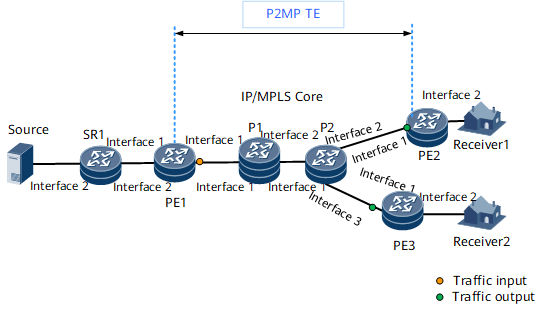
A P2MP TE tunnel is established on the network shown in Figure 1. PE1 is the tunnel ingress. PE2, and PE3 are leaf nodes, and the tunnel bandwidth is 1000 kbit/s. For the IP address of each node, see Table 1.

Interfaces 1, 2, 3, and 4 in this example represent GE 0/1/0, GE 0/1/8, and GE 0/1/16, respectively.
Device |
Interface |
IP Address |
Device |
Interface |
IP Address |
|---|---|---|---|---|---|
PE1 |
GE 0/1/0 |
10.1.1.1/24 |
PE2 |
GE 0/1/0 |
10.4.1.2/24 |
GE 0/1/8 |
10.7.1.1/24 |
GE 0/1/8 |
10.9.1.1/24 |
||
Loopback 1 |
1.1.1.1/32 |
Loopback 1 |
5.5.5.5/32 |
||
P1 |
GigabitEthernet0/1/0 |
10.1.1.2/24 |
P2 |
GigabitEthernet0/1/0 |
10.2.1.2/24 |
GigabitEthernet0/1/8 |
10.2.1.1/24 |
GigabitEthernet0/1/8 |
10.4.1.1/24 |
||
Loopback 1 |
2.2.2.2/32 |
GigabitEthernet 0/1/16 |
10.5.1.1/24 |
||
SR1 |
GE 0/1/0 |
10.7.1.2/24 |
Loopback 1 |
4.4.4.4/32 |
|
GE 0/1/8 |
10.8.1.2/24 |
PE3 |
GE 0/1/0 |
10.5.1.2/24 |
|
Loopback 1 |
3.3.3.3/32 |
GE 0/1/8 |
10.10.1.1/24 |
||
Source |
Loopback 1 |
8.8.8.8/32 |
Loopback 1 |
6.6.6.6/32 |
Precautions
When you configure multicast, enable IGMP on the PE interface connected to multicast data receivers.
Configuration Roadmap
The configuration roadmap is as follows:
Assign an IP address to each interface and configure a loopback interface address as an LSR ID on each node.
Configure Intermediate System to Intermediate System (IS-IS) to advertise the route to each network segment of each interface and the host route to each loopback interface address that is an LSR ID.
Enable MPLS, MPLS TE, and MPLS Resource Reservation Protocol (RSVP) globally on each node and constraint shortest path first (CSPF) on the ingress to enable all nodes to have MPLS forwarding capabilities.
Enable the IS-IS TE capability to ensure that MPLS TE can advertise information about link status.
Enable the MPLS TE capability on the interfaces of each node, and configure link attributes for the interfaces so that the interfaces can send RSVP signaling packets.
Configure explicit paths and a leaf list on the ingress PE1 to specify the leaf nodes on the P2MP TE tunnel.
Configure a P2MP TE tunnel interface on PE1 to ensure that the ingress establishes a P2MP TE tunnel based on all configuration information on the interface.
Enable multicast on the device connected to the multicast source, ingress, and egresses.
On PE1, direct multicast traffic to the P2MP TE tunnel. On PE2 and PE3, direct multicast traffic out of the P2MP TE tunnel.
Data Preparation
To complete the configuration, you need the following data:
IP addresses of all interfaces shown in Figure 1
IS-IS (used as an IGP protocol), IS-IS process ID (1), IS-IS system ID of each node (obtained by translating the IP address of loopback1 of each node), and IS-IS level (Level-2)
MPLS LSR ID of each node using the corresponding loopback interface address
Maximum reservable bandwidth (10000 kbit/s) of the outbound interface along the path and BC0 bandwidth (10000 kbit/s)
Name of an explicit path used by each leaf node (tope1, tope2, and tope3), name of the leaf list (iptv1), and addresses of each leaf node (MPLS LSR ID of each leaf node)
Tunnel interface number (Tunnel 10), tunnel ID (100), loopback interface address used as the IP address of the tunnel interface, and tunnel bandwidth (1000 kbit/s)
Procedure
- Configure IP addresses for the interfaces.
Configure IP addresses for the interfaces according to Figure 1, and create a loopback interface on each node. For configuration details, see Configuration Files in this section.
- Configure IS-IS to advertise the route to each network segment of each interface and to advertise the host route to each LSR ID.
Configure IS-IS on each node to allow the nodes to communicate at the network layer. For configuration details, see Configuration Files in this section.
- Enable MPLS, MPLS TE, and MPLS RSVP globally on each node and CSPF on the ingress.
# Configure PE1.
<PE1> system-view
[~PE1] mpls lsr-id 1.1.1.1
[*PE1] mpls
[*PE1-mpls] mpls te
[*PE1-mpls] mpls te p2mp-te
[*PE1-mpls] mpls rsvp-te
[*PE1-mpls] mpls te cspf
[*PE1-mpls] commit
[~PE1-mpls] quit
# Configure P1.
<P1> system-view
[~P1] mpls lsr-id 2.2.2.2
[*P1] mpls
[*P1-mpls] mpls te
[*P1-mpls] mpls te p2mp-te
[*P1-mpls] mpls rsvp-te
[*P1-mpls] mpls te cspf
[*P1-mpls] commit
[~P1-mpls] quit
# Configure P2.
<P2> system-view
[~P2] mpls lsr-id 4.4.4.4
[*P2] mpls
[*P2-mpls] mpls te
[*P2-mpls] mpls te p2mp-te
[*P2-mpls] mpls rsvp-te
[*P2-mpls] mpls te cspf
[*P2-mpls] commit
[~P2-mpls] quit
# Configure PE2.
<PE2> system-view
[~PE2] mpls lsr-id 5.5.5.5
[*PE2] mpls
[*PE2-mpls] mpls te
[*PE2-mpls] mpls te p2mp-te
[*PE2-mpls] mpls rsvp-te
[*PE2-mpls] mpls te cspf
[*PE2-mpls] commit
[~PE2-mpls] quit
# Configure PE3.
<PE3> system-view
[~PE3] mpls lsr-id 6.6.6.6
[*PE3] mpls
[*PE3-mpls] mpls te
[*PE3-mpls] mpls te p2mp-te
[*PE3-mpls] mpls rsvp-te
[*PE3-mpls] mpls te cspf
[*PE3-mpls] commit
[~PE3-mpls] quit
- Enable IS-IS TE on each node.
# Configure PE1.
[~PE1] isis 1
[*PE1-isis-1] cost-style wide
[*PE1-isis-1] traffic-eng level-2
[*PE1-isis-1] commit
[~PE1-isis-1] quit
# Configure P1.
[~P1] isis 1
[*P1-isis-1] cost-style wide
[*P1-isis-1] traffic-eng level-2
[*P1-isis-1] commit
[~P1-isis-1] quit
# Configure P2.
[~P2] isis 1
[*P2-isis-1] cost-style wide
[*P2-isis-1] traffic-eng level-2
[*P2-isis-1] commit
[~P2-isis-1] quit
# Configure PE2.
[~PE2] isis 1
[*PE2-isis-1] cost-style wide
[*PE2-isis-1] traffic-eng level-2
[*PE2-isis-1] commit
[~PE2-isis-1] quit
# Configure PE3.
[~PE3] isis 1
[*PE3-isis-1] cost-style wide
[*PE3-isis-1] traffic-eng level-2
[*PE3-isis-1] commit
[~PE3-isis-1] quit
- Enable the MPLS TE capability on the interface of each node, and configure link attributes for the interfaces.
# Configure PE1.
<PE1> system-view
[~PE1] interface gigabitethernet 0/1/0
[~PE1-GigabitEthernet0/1/0] mpls
[*PE1-GigabitEthernet0/1/0] mpls te
[*PE1-GigabitEthernet0/1/0] mpls rsvp-te
[*PE1-GigabitEthernet0/1/0] mpls te bandwidth max-reservable-bandwidth 10000
[*PE1-GigabitEthernet0/1/0] mpls te bandwidth bc0 10000
[*PE1-GigabitEthernet0/1/0] commit
[~PE1-GigabitEthernet0/1/0] quit
# Configure P1.
<P1> system-view
[~P1] interface gigabitethernet 0/1/8
[~P1-GigabitEthernet0/1/8] mpls
[*P1-GigabitEthernet0/1/8] mpls te
[*P1-GigabitEthernet0/1/8] mpls rsvp-te
[*P1-GigabitEthernet0/1/8] mpls te bandwidth max-reservable-bandwidth 10000
[*P1-GigabitEthernet0/1/8] mpls te bandwidth bc0 10000
[*P1-GigabitEthernet0/1/8] quit
[*P1] interface gigabitethernet 0/1/0
[*P1-GigabitEthernet0/1/0] mpls
[*P1-GigabitEthernet0/1/0] mpls te
[*P1-GigabitEthernet0/1/0] mpls rsvp-te
[*P1-GigabitEthernet0/1/0] mpls te bandwidth max-reservable-bandwidth 10000
[*P1-GigabitEthernet0/1/0] mpls te bandwidth bc0 10000
[*P1-GigabitEthernet0/1/0] commit
[~P1-GigabitEthernet0/1/0] quit
# Configure P2.
<P2> system-view
[~P2] interface gigabitethernet 0/1/0
[~P2-GigabitEthernet0/1/0] mpls
[*P2-GigabitEthernet0/1/0] mpls te
[*P2-GigabitEthernet0/1/0] mpls rsvp-te
[*P2-GigabitEthernet0/1/0] mpls te bandwidth max-reservable-bandwidth 10000
[*P2-GigabitEthernet0/1/0] mpls te bandwidth bc0 10000
[*P2-GigabitEthernet0/1/0] quit
[*P2] interface gigabitethernet 0/1/8
[*P2-GigabitEthernet0/1/8] mpls
[*P2-GigabitEthernet0/1/8] mpls te
[*P2-GigabitEthernet0/1/8] mpls rsvp-te
[*P2-GigabitEthernet0/1/8] mpls te bandwidth max-reservable-bandwidth 10000
[*P2-GigabitEthernet0/1/8] mpls te bandwidth bc0 10000
[*P2-GigabitEthernet0/1/8] quit
[*P2] interface gigabitethernet 0/1/16
[*P2-GigabitEthernet0/1/16] mpls
[*P2-GigabitEthernet0/1/16] mpls te
[*P2-GigabitEthernet0/1/16] mpls rsvp-te
[*P2-GigabitEthernet0/1/16] mpls te bandwidth max-reservable-bandwidth 10000
[*P2-GigabitEthernet0/1/16] mpls te bandwidth bc0 10000
[*P2-GigabitEthernet0/1/16] commit
[~P2-GigabitEthernet0/1/16] quit
# Configure PE2.
<PE2> system-view
[~PE2] interface gigabitethernet 0/1/0
[~PE2-GigabitEthernet0/1/0] mpls
[*PE2-GigabitEthernet0/1/0] mpls te
[*PE2-GigabitEthernet0/1/0] mpls rsvp-te
[*PE2-GigabitEthernet0/1/0] mpls te bandwidth max-reservable-bandwidth 10000
[*PE2-GigabitEthernet0/1/0] mpls te bandwidth bc0 10000
[*PE2-GigabitEthernet0/1/0] commit
[~PE2-GigabitEthernet0/1/0] quit
# Configure PE3.
<PE3> system-view
[~PE3] interface gigabitethernet 0/1/0
[~PE3-GigabitEthernet0/1/0] mpls
[*PE3-GigabitEthernet0/1/0] mpls te
[*PE3-GigabitEthernet0/1/0] mpls rsvp-te
[*PE3-GigabitEthernet0/1/0] mpls te bandwidth max-reservable-bandwidth 10000
[*PE3-GigabitEthernet0/1/0] mpls te bandwidth bc0 10000
[*PE3-GigabitEthernet0/1/0] commit
[~PE3-GigabitEthernet0/1/0] quit
- Configure explicit paths and a leaf list on the ingress PE1.
# Configure explicit paths on PE1 to PE2, and PE3.
[~PE1] explicit-path tope3
[*PE1-explicit-path-tope3] next hop 10.1.1.2
[*PE1-explicit-path-tope3] next hop 10.2.1.2
[*PE1-explicit-path-tope3] next hop 10.5.1.2
[*PE1-explicit-path-tope3] commit
[~PE1-explicit-path-tope3] quit
[~PE1] explicit-path tope2
[*PE1-explicit-path-tope2] next hop 10.1.1.2
[*PE1-explicit-path-tope2] next hop 10.2.1.2
[*PE1-explicit-path-tope2] next hop 10.4.1.2
[*PE1-explicit-path-tope2] commit
[~PE1-explicit-path-tope2] quit
# Configure a leaf list iptv1 on PE1 and add leaf node addresses to the leaf list.
[~PE1] mpls te leaf-list iptv1
[*PE1-mpls-te-leaf-list-iptv1] destination 5.5.5.5
[*PE1-mpls-te-leaf-list-iptv1-destination-5.5.5.5] path explicit-path tope2
[*PE1-mpls-te-leaf-list-iptv1-destination-5.5.5.5] quit
[*PE1-mpls-te-leaf-list-iptv1] destination 6.6.6.6
[*PE1-mpls-te-leaf-list-iptv1-destination-6.6.6.6] path explicit-path tope3
[*PE1-mpls-te-leaf-list-iptv1-destination-6.6.6.6] commit
[~PE1-mpls-te-leaf-list-iptv1-destination-6.6.6.6] quit
[~PE1-mpls-te-leaf-list-iptv1] quit
- Configure the P2MP TE tunnel interface on the ingress PE1.
# Configure PE1.
[~PE1] interface Tunnel 10
[*PE1-Tunnel10] ip address unnumbered interface loopback 1
[*PE1-Tunnel10] tunnel-protocol mpls te
[*PE1-Tunnel10] mpls te p2mp-mode
[*PE1-Tunnel10] mpls te tunnel-id 100
[*PE1-Tunnel10] mpls te leaf-list iptv1
[*PE1-Tunnel10] mpls te bandwidth ct0 1000
[*PE1-Tunnel10] commit
[~PE1-Tunnel10] quit
After completing the configurations, a P2MP TE tunnel is configured.
- Enable multicast on the device connected to the multicast source, ingress, and egresses.
# Configure SR1.
[~SR1] multicast routing-enable
[*SR1] interface gigabitethernet 0/1/0
[*SR1-GigabitEthernet0/1/0] pim sm
[*SR1-GigabitEthernet0/1/0] quit
[*SR1] interface gigabitethernet 0/1/8
[*SR1-GigabitEthernet0/1/8] pim sm
[*SR1-GigabitEthernet0/1/8] quit
[*SR1] commit
# Configure PE1.
[~PE1] multicast routing-enable
[*PE1] interface gigabitethernet 0/1/8
[*PE1-GigabitEthernet0/1/8] pim sm
[*PE1-GigabitEthernet0/1/8] quit
[*PE1] commit
# Configure PE2. When you configure basic PIM-SM functions on PE2 interfaces, enable IGMP on the PE2 interface connected to multicast data receivers.
[~PE2] multicast routing-enable
[*PE2] interface gigabitethernet 0/1/8
[*PE2-GigabitEthernet0/1/8] pim sm
[*PE2-GigabitEthernet0/1/8] igmp enable
[*PE2-GigabitEthernet0/1/8] quit
[*PE2] commit
# Configure PE3. When you configure basic PIM-SM functions on PE3 interfaces, enable IGMP on the PE3 interface connected to multicast data receivers.
[~PE3] multicast routing-enable
[*PE3] interface gigabitethernet 0/1/8
[*PE3-GigabitEthernet0/1/8] pim sm
[*PE3-GigabitEthernet0/1/8] igmp enable
[*PE3-GigabitEthernet0/1/8] quit
[*PE3] commit
After the preceding operations are complete, the multicast network can operate properly.
- Direct multicast traffic into and out of a P2MP TE tunnel.
On PE1, direct multicast traffic to the P2MP TE tunnel.
# Configure PE1.
[~PE1] interface Tunnel10
[*PE1-Tunnel10] pim sm
[*PE1-Tunnel10] igmp static-group 226.1.1.1 source 8.8.8.8
[*PE1-Tunnel10] commit
[~PE1-Tunnel10] quit
On PE2 and PE3, direct multicast traffic out of the P2MP TE tunnel.
# Configure PE2.
[~PE2] pim
[*PE2-pim] rpf disable all
[*PE2-pim] traffic select p2mp-te root-ip 1.1.1.1 tunnel-id 100
[*PE2-pim] commit
[~PE2-pim] quit
# Configure PE3.
[~PE3] pim
[*PE3-pim] rpf disable all
[*PE3-pim] traffic select p2mp-te root-ip 1.1.1.1 tunnel-id 100
[*PE3-pim] commit
[~PE3-pim] quit
- Verify the configuration.
Receivers can receive multicast data from the multicast source.
# Run the igmp static-group command on PE2 to configure an interface to statically join multicast groups.
[~PE2] interface gigabitethernet 0/1/8
[~PE2-GigabitEthernet0/1/8] igmp static-group 226.1.1.1 source 8.8.8.8
[*PE2-GigabitEthernet0/1/8] commit
[~PE2-GigabitEthernet0/1/8] quit
# Run the display pim routing-table command on PE2 to view source/group information.
[~PE2] display pim routing-table
VPN-Instance: public net
Total 0 (*, G) entry; 1 (S, G) entries                                                                                                                                                                                                                           (8.8.8.8, 226.1.1.1)
RP: NULL
Protocol: pim-sm, Flag: SPT SG_RCVR NORPF
UpTime: 00:00:06
Upstream interface: Mcast_In_IF, Refresh time: 00:00:06                                                                                                    Upstream neighbor: NULL
RPF prime neighbor: NULL
     Downstream interface(s) information:
Total number of downstreams: 1
1: GigabitEthernet0/1/8
    Protocol: static, UpTime: 00:00:06, Expires: -
The preceding command output shows that receiver can receive multicast data from the multicast source, indicating that multicast has been configured successfully.
Configuration Files
SR1 configuration file
#
sysname SR1
#
multicast routing-enable
#
isis 1
 is-level level-2
 cost-style wide
 network-entity 00.0005.0000.0000.0003.00
 traffic-eng level-2
#
interface GigabitEthernet0/1/0
 undo shutdown
 ip address 10.7.1.2 255.255.255.0
 pim sm
 isis enable 1
#
interface GigabitEthernet0/1/8
 undo shutdown
 ip address 10.8.1.1 255.255.255.0
 pim sm
 isis enable 1
#
interface LoopBack1
 ip address 3.3.3.3 255.255.255.255
 isis enable 1
#
return
PE1 configuration file
#
sysname PE1
#
multicast routing-enable
#
mpls lsr-id 1.1.1.1
#
mpls
 mpls te
 mpls te p2mp-te
 mpls rsvp-te
 mpls te cspf
#
explicit-path tope3
 next hop 10.1.1.2
 next hop 10.2.1.2
 next hop 10.5.1.2
#
explicit-path tope2
 next hop 10.1.1.2
 next hop 10.2.1.2
 next hop 10.4.1.2
#
mpls te leaf-list iptv1
 #
 destination 5.5.5.5
  path explicit-path tope2
 #
 destination 6.6.6.6
  path explicit-path tope3
#
isis 1
 is-level level-2
 cost-style wide
 network-entity 00.0005.0000.0000.0001.00
 traffic-eng level-2
#
interface GigabitEthernet0/1/0
 undo shutdown
 ip address 10.1.1.1 255.255.255.0
 isis enable 1
 mpls
 mpls te
 mpls te bandwidth max-reservable-bandwidth 10000
 mpls te bandwidth bc0 10000
 mpls rsvp-te
#
interface GigabitEthernet0/1/8
 undo shutdown
 ip address 10.7.1.1 255.255.255.0
 pim sm
 isis enable 1
#
interface LoopBack1
 ip address 1.1.1.1 255.255.255.255
 isis enable 1
#
interface Tunnel10
 ip address unnumbered interface LoopBack1
 tunnel-protocol mpls te
 pim sm
 igmp static-group 226.1.1.1 source 8.8.8.8
 mpls te p2mp-mode
 mpls te bandwidth ct0 1000
 mpls te leaf-list iptv1
 mpls te tunnel-id 100
#
return
P1 configuration file
#
sysname P1
#
mpls lsr-id 2.2.2.2
#
mpls
 mpls te
 mpls te p2mp-te
 mpls rsvp-te
 mpls te cspf
#
isis 1
 is-level level-2
 cost-style wide
 network-entity 00.0005.0000.0000.0002.00
 traffic-eng level-2
#
interface GigabitEthernet0/1/8
 undo shutdown
 ip address 10.2.1.1 255.255.255.0
 isis enable 1
 mpls
 mpls te
 mpls te bandwidth max-reservable-bandwidth 10000
 mpls te bandwidth bc0 10000
 mpls rsvp-te
#
interface GigabitEthernet0/1/0
 undo shutdown
 ip address 10.1.1.2 255.255.255.0
 isis enable 1
 mpls
 mpls te
 mpls te bandwidth max-reservable-bandwidth 10000
 mpls te bandwidth bc0 10000
 mpls rsvp-te
#
interface LoopBack1
 ip address 2.2.2.2 255.255.255.255
 isis enable 1
#
return
P2 configuration file
#
sysname P2
#
mpls lsr-id 4.4.4.4
#
mpls
 mpls te
 mpls te p2mp-te
 mpls rsvp-te
 mpls te cspf
#
isis 1
 is-level level-2
 cost-style wide
 network-entity 00.0005.0000.0000.0004.00
 traffic-eng level-2
#
interface GigabitEthernet0/1/0
 undo shutdown
 ip address 10.2.1.2 255.255.255.0
 isis enable 1
 mpls
 mpls te
 mpls te bandwidth max-reservable-bandwidth 10000
 mpls te bandwidth bc0 10000
 mpls rsvp-te
#
interface GigabitEthernet0/1/8
 undo shutdown
 ip address 10.4.1.1 255.255.255.0
 isis enable 1
 mpls
 mpls te
 mpls te bandwidth max-reservable-bandwidth 10000
 mpls te bandwidth bc0 10000
 mpls rsvp-te
#
interface GigabitEthernet0/1/16
 undo shutdown
 ip address 10.5.1.1 255.255.255.0
 isis enable 1
 mpls
 mpls te
 mpls te bandwidth max-reservable-bandwidth 10000
 mpls te bandwidth bc0 10000
 mpls rsvp-te
#
interface LoopBack1
 ip address 4.4.4.4 255.255.255.255
 isis enable 1
#
return
PE2 configuration file
#
sysname PE2
#
multicast routing-enable
#
mpls lsr-id 5.5.5.5
#
mpls
 mpls te
 mpls te p2mp-te
 mpls rsvp-te
 mpls te cspf
#
isis 1
 is-level level-2
 cost-style wide
 network-entity 00.0005.0000.0000.0005.00
 traffic-eng level-2
#
interface GigabitEthernet0/1/0
 undo shutdown
 ip address 10.4.1.2 255.255.255.0
 isis enable 1
 mpls
 mpls te
 mpls te bandwidth max-reservable-bandwidth 10000
 mpls te bandwidth bc0 10000
 mpls rsvp-te
#
interface GigabitEthernet0/1/8
 undo shutdown
 ip address 10.9.1.1 255.255.255.0
 pim sm
 igmp enable
 igmp static-group 226.1.1.1 source 8.8.8.8
 isis enable 1
#
interface LoopBack1
 ip address 5.5.5.5 255.255.255.255
 isis enable 1
#
pim
 rpf disable all
 traffic select p2mp-te root-ip 1.1.1.1 tunnel-id 100
#
return
PE3 configuration file
#
sysname PE3
#
multicast routing-enable
#
mpls lsr-id 6.6.6.6
#
mpls
 mpls te
 mpls te p2mp-te
 mpls rsvp-te
 mpls te cspf
#
isis 1
 is-level level-2
 cost-style wide
 network-entity 00.0005.0000.0000.0006.00
 traffic-eng level-2
#
interface GigabitEthernet0/1/0
 undo shutdown
 ip address 10.5.1.2 255.255.255.0
 isis enable 1
 mpls
 mpls te
 mpls te bandwidth max-reservable-bandwidth 10000
 mpls te bandwidth bc0 10000
 mpls rsvp-te
#
interface GigabitEthernet0/1/8
 undo shutdown
 ip address 10.10.1.1 255.255.255.0
 pim sm
 igmp enable
 isis enable 1
#
interface LoopBack1
 ip address 6.6.6.6 255.255.255.255
 isis enable 1
#
pim
 rpf disable all
 traffic select p2mp-te root-ip 1.1.1.1 tunnel-id 100
#
return