Example for Configuring PIM over GRE
This section provides an example for configuring PIM over GRE.
Networking Requirements
On the multicast network shown in Figure 1, a GRE tunnel is established between Device A and Device B to carry multicast traffic.
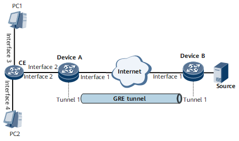
Interfaces 1, 2, 3, and 4 in this example represent GE 0/1/1, GE 0/1/2, GE 0/1/3, and GE 0/1/4, respectively.
Device Name |
Interface |
IP Address |
|---|---|---|
Device A |
GE 0/1/1 |
10.1.1.1/24 |
GE 0/1/2 |
10.1.6.1/24 |
|
Loopback 1 |
192.168.1.1/32 |
|
Tunnel 1 |
10.0.1.1/32 |
|
Device B |
GE 0/1/1 |
10.1.1.19/24 |
GE 0/1/2 |
10.1.5.1/24 |
|
Loopback 1 |
192.168.1.2/32 |
|
Tunnel 1 |
10.0.1.2/32 |
|
CE |
GE 0/1/2 |
10.1.6.2/24 |
GE 0/1/3 |
10.1.7.1/24 |
|
GE 0/1/4 |
10.1.8.1/24 |
Configuration Roadmap
Assign IP addresses to router interfaces and configure a unicast routing protocol. Run OSPF on the network between Device A and Device B, and set an OSPF process ID and area ID to 1 and 0.0.0.0, respectively. Run OSPF on the network where multicast users are connected to Device A. Set an OSPF process ID and area ID to 1 and 0.0.0.1, respectively.
Create a GRE tunnel between Device A and Device B so that data is transmitted between them through the GRE tunnel.
Enable the multicast function on all routers providing multicast services.
Enable PIM-SM on the interface connecting Device A to the user network, the interface connecting Device B to the multicast source, and all GRE tunnel interfaces. Enable PIM-SM on the interface connecting the CE to Device A, and enable PIM-SM and IGMP on the interfaces connecting the CE to multicast users.
Data Preparation
To complete the configuration, you need the following data:
GRE tunnel's source and destination addresses on each end
Tunnel interfaces' IP addresses on each end
IP addresses of router interfaces
Procedure
- Assign IP addresses to router interfaces and configure a unicast routing protocol. For configuration details, see Configuration Files.
- Configure tunnel interfaces.
# Configure Device A.
[~DeviceA] interface loopback1
[*DeviceA-LoopBack1] binding tunnel gre
[*DeviceA-LoopBack1] commit
[~DeviceA-LoopBack1] quit
[~DeviceA] interface tunnel 1
[*DeviceA-Tunnel1] tunnel-protocol gre
[*DeviceA-Tunnel1] ip address 10.0.1.1 255.255.255.0
[*DeviceA-Tunnel1] source 192.168.1.1
[*DeviceA-Tunnel1] destination 192.168.1.2
[*DeviceA-Tunnel1] quit
[*DeviceA] commit
# Configure Device B.
[~DeviceB] interface loopback1
[*DeviceB-LoopBack1] binding tunnel gre
[*DeviceB-LoopBack1] commit
[~DeviceB-LoopBack1] quit
[~DeviceB] interface tunnel 1
[*DeviceB-Tunnel1] tunnel-protocol gre
[*DeviceB-Tunnel1] ip address 10.0.1.2 255.255.255.0
[*DeviceB-Tunnel1] source 192.168.1.2
[*DeviceB-Tunnel1] destination 192.168.1.1
[*DeviceB-Tunnel1] quit
[*DeviceB] commit
After the configuration is complete, the tunnel interfaces go Up and can ping each other.
# The following example uses the command output on Device A.
[~DeviceA] ping -a 10.0.1.1 10.0.1.2
  PING 10.0.1.2: 56  data bytes, press CTRL_C to break
    Reply from 10.0.1.2: bytes=56 Sequence=1 ttl=255 time=24 ms
    Reply from 10.0.1.2: bytes=56 Sequence=2 ttl=255 time=33 ms
    Reply from 10.0.1.2: bytes=56 Sequence=3 ttl=255 time=48 ms
    Reply from 10.0.1.2: bytes=56 Sequence=4 ttl=255 time=33 ms
    Reply from 10.0.1.2: bytes=56 Sequence=5 ttl=255 time=36 ms
  --- 10.0.1.2 ping statistics ---
    5 packet(s) transmitted
    5 packet(s) received
    0.00% packet loss
    round-trip min/avg/max = 24/34/48 ms
- Configure static routes for the tunnel interfaces.
# Configure Device A.
[~DeviceA] ip route-static 10.1.5.0 255.255.255.0 Tunnel1 10.0.1.2
[*DeviceA] commit
# Configure Device B.
[~DeviceB] ip route-static 10.1.6.0 255.255.255.0 Tunnel1 10.0.1.1
[*DeviceB] ip route-static 10.1.7.0 255.255.255.0 Tunnel1 10.0.1.1
[*DeviceB] ip route-static 10.1.8.0 255.255.255.0 Tunnel1 10.0.1.1
[*DeviceB] commit
- Enable the multicast function on each router, and enable PIM-SM on router interfaces.
# Configure the CE. The configurations on Device A and Device B are similar to the configuration on the CE. For configuration details, see Configuration Files.
[~CE] multicast routing-enable
[*CE] interface gigabitethernet 0/1/2
[*CE-GigabitEthernet0/1/2] pim sm
[*CE-GigabitEthernet0/1/2] quit
[*CE] interface gigabitethernet 0/1/3
[*CE-GigabitEthernet0/1/3] pim sm
[*CE-GigabitEthernet0/1/3] quit
[*CE] interface gigabitethernet 0/1/4
[*CE-GigabitEthernet0/1/4] pim sm
[*CE-GigabitEthernet0/1/4] commit
[~CE-GigabitEthernet0/1/4] quit
- # Enable IGMP on the interfaces connecting the CE to the PCs.
[~CE] interface gigabitethernet 0/1/3
[~CE-GigabitEthernet0/1/3] igmp enable
[*CE-GigabitEthernet0/1/3] igmp version 3
[*CE-GigabitEthernet0/1/3] commit
[~CE-GigabitEthernet0/1/3] quit
[*CE] interface gigabitethernet 0/1/4
[*CE-GigabitEthernet0/1/4] igmp enable
[*CE-GigabitEthernet0/1/4] igmp version 3
[*CE-GigabitEthernet0/1/4] commit
[~CE-GigabitEthernet0/1/4] quit
- Verify the configuration.
# On the CE's GE 0/1/3, configure IGMP users to statically join the multicast group 232.1.1.1, with the multicast source set to 10.1.5.10.
[~CE] interface gigabitethernet 0/1/3
[~CE-GigabitEthernet0/1/3] igmp static-group 232.1.1.1 source 10.1.5.10
[*CE-GigabitEthernet0/1/3] commit
[~CE-GigabitEthernet0/1/3] quit
# View PIM routing information on Device A and Device B.
<DeviceA> display pim routing-table
 VPN-Instance: public net
 Total 1 (S, G) entry

 (10.1.5.10, 232.1.1.1)
     Protocol: pim-ssm, Flag:
     UpTime: 00:01:14
     Upstream interface: Tunnel1, Refresh time: 00:01:14
         Upstream neighbor: 10.0.1.2
         RPF prime neighbor: 10.0.1.2
     Downstream interface(s) information:
     Total number of downstreams: 1
        1: GigabitEthernet0/1/2
             Protocol: pim-ssm, UpTime: 00:01:14, Expires: 00:03:16
<DeviceB> display pim routing-table
 VPN-Instance: public net
 Total 1 (S, G) entry

 (10.1.5.10, 232.1.1.1)
     Protocol: pim-ssm, Flag: LOC
     UpTime: 00:00:41
     Upstream interface: GigabitEthernet0/1/2, Refresh time: 00:00:41
         Upstream neighbor: NULL
         RPF prime neighbor: NULL
     Downstream interface(s) information:
     Total number of downstreams: 1
        1: Tunnel1
             Protocol: pim-ssm, UpTime: 00:00:41, Expires: 00:02:49
Configuration Files
Device A configuration file
#
sysname DeviceA
#
multicast routing-enable
#
interface GigabitEthernet0/1/1
 undo shutdown
 ip address 10.1.1.1 255.255.255.0
#
interface GigabitEthernet0/1/2
 undo shutdown
 ip address 10.1.6.1 255.255.255.0
 pim sm
#
interface LoopBack1
 ip address 192.168.1.1 255.255.255.255
 binding tunnel gre
#
interface Tunnel1
 ip address 10.0.1.1 255.255.255.0
 tunnel-protocol gre
 source 192.168.1.1
 destination 192.168.1.2
 pim sm
#
interface NULL0
#
ospf 1
 area 0.0.0.0
  network 10.1.1.0 0.0.0.255
  network 192.168.1.1 0.0.0.0
 area 0.0.0.1
  network 10.1.6.0 0.0.0.255
#
pim
 static-rp 10.0.1.1
#
ip route-static 10.1.5.0 255.255.255.0 Tunnel1 10.0.1.2
#
return
Device B configuration file
#
sysname DeviceB
#
multicast routing-enable
#
interface GigabitEthernet0/1/1
 undo shutdown
 ip address 10.1.1.19 255.255.255.0
#
interface GigabitEthernet0/1/2
 undo shutdown
 ip address 10.1.5.1 255.255.255.0
 pim sm
#
interface LoopBack1
 ip address 192.168.1.2 255.255.255.255
 binding tunnel gre
#
interface Tunnel1
 ip address 10.0.1.2 255.255.255.0
 tunnel-protocol gre
 source 192.168.1.2
 destination 192.168.1.1
 pim sm
#
interface NULL0
#
ospf 1
 area 0.0.0.0
  network 10.1.1.0 0.0.0.255
  network 192.168.1.2 0.0.0.0
#
pim
 static-rp 10.0.1.1
#
ip route-static 10.1.6.0 255.255.255.0 Tunnel1 10.0.1.1
ip route-static 10.1.7.0 255.255.255.0 Tunnel1 10.0.1.1
ip route-static 10.1.8.0 255.255.255.0 Tunnel1 10.0.1.1
#
return
CE configuration file
#
sysname CE
#
multicast routing-enable
#
interface GigabitEthernet0/1/2
 undo shutdown
 ip address 10.1.6.2 255.255.255.0
 pim sm
#
interface GigabitEthernet0/1/3
 undo shutdown
 ip address 10.1.7.1 255.255.255.0
 pim sm
 igmp enable
 igmp version 3
 igmp static-group 232.1.1.1 source 10.1.5.10
#
interface GigabitEthernet0/1/4
 undo shutdown
 ip address 10.1.8.1 255.255.255.0
 pim sm
 igmp enable
 igmp version 3
#
interface NULL0
#
ospf 1
 area 0.0.0.1
  network 10.1.6.0 0.0.0.255
  network 10.1.7.0 0.0.0.255
  network 10.1.8.0 0.0.0.255
#
pim
 static-rp 10.0.1.1
#
ip route-static 0.0.0.0 0.0.0.0 10.1.6.1
#
return