Example for Configuring MVPN Extranet in the Local Route leaking Scenario Where the Multicast Source Belongs to the Public Network Instance
This section provides an example for configuring MVPN Extranet in the local route leaking scenario where the multicast source belongs to the public network instance.
Networking Requirements
MD MVPN supports only intra-VPN multicast service distribution. In real-world application, however, a service provider may need to provide multicast services to users in a different VPN than its own VPN. This requires inter-VPN multicast distribution.
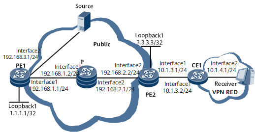
In the local route leaking scenario shown in Figure 1, the multicast source belongs to the public network instance and the receiver belongs to VPN RED. The receiver requires multicast data from the source in the public network instance. To meet this requirement, deploy MVPN extranet.
Configuration Roadmap
The configuration roadmap is as follows:
Configure a unicast routing protocol on the public network and enable the multicast function, ensuring normal multicast routing on the public network.
Configure a VPN instance (VPN RED) enabled with the IPv4 address family on PE2, set the share-group address for the VPN instance, and create an MTunnel interface. Bind the interface connecting PE2 to CE1 to the VPN instance.
Configure a unicast routing protocol on the public network and enable the multicast function in the VPN instance, ensuring normal multicast routing in the VPN instance.
Configure a unicast routing protocol between a PE and a CE to ensure that the PE and the CE are routable.
On PE, bind the VPN instance to an MTunnel interface.
Configure a Rendezvous Point (RP) to serve the multicast groups running the multicast VPN extranet service.
Configure static routes between the VPN instance and Source and between the VPN instance and RP on the public network.
Data Preparation
To complete the configuration, you need the following data:
RD and RT of VPN RED: 300:1
Share-group address of VPN RED: 238.0.0.0
Multicast group address used by the VPN extranet: 228.0.0.1
Procedure
- Configure OSPF and multicast on the public network to ensure that the multicast routes on the network are reachable.
# Configure PE1.
<HUAWEI> system-view
[~HUAWEI] sysname PE1
[*HUAWEI] commit
[~PE1] multicast routing-enable
[*PE1] interface loopback 1
[*PE1-LoopBack1] ip address 1.1.1.1 32
[*PE1-LoopBack1] pim sm
[*PE1-LoopBack1] quit
[*PE1] interface gigabitethernet 0/1/0
[*PE1-Gigabitethernet0/1/0] ip address 192.168.1.1 24
[*PE1-Gigabitethernet0/1/0] pim sm
[*PE1-Gigabitethernet0/1/0] quit
[*PE1] interface gigabitethernet 0/1/8
[*PE1-GigabitEthernet0/1/8] ip address 192.168.3.1 24
[*PE1-GigabitEthernet0/1/8] pim sm
[*PE1-GigabitEthernet0/1/8] quit
[*PE1] ospf
[*PE1-ospf-1] area 0
[*PE1-ospf-1-area-0.0.0.0] network 1.1.1.1 0.0.0.0
[*PE1-ospf-1-area-0.0.0.0] network 192.168.1.0 0.0.0.255
[*PE1-ospf-1-area-0.0.0.0] network 192.168.3.0 0.0.0.255
[*PE1-ospf-1-area-0.0.0.0] quit
[*PE1-ospf-1] quit
[*PE1] commit
# Configure the P.
<HUAWEI> system-view
[~HUAWEI] sysname P
[*HUAWEI] commit
[~P] multicast routing-enable
[*P] interface gigabitethernet 0/1/0
[*P-Gigabitethernet0/1/0] ip address 192.168.1.2 24
[*P-Gigabitethernet0/1/0] pim sm
[*P-Gigabitethernet0/1/0] quit
[*P] interface gigabitethernet 0/1/8
[*P-GigabitEthernet0/1/8] ip address 192.168.2.1 24
[*P-GigabitEthernet0/1/8] pim sm
[*P-GigabitEthernet0/1/8] quit
[*P] ospf
[*P-ospf-1] area 0
[*P-ospf-1-area-0.0.0.0] network 192.168.1.0 0.0.0.255
[*P-ospf-1-area-0.0.0.0] network 192.168.2.0 0.0.0.255
[*P-ospf-1-area-0.0.0.0] quit
[*P-ospf-1] quit
[*P] commit
# Configure PE2.
<HUAWEI> system-view
[~HUAWEI] sysname PE2
[*HUAWEI] commit
[~PE2] multicast routing-enable
[*PE2] interface loopback 1
[*PE2-LoopBack1] ip address 3.3.3.3 32
[*PE2-LoopBack1] pim sm
[*PE2-LoopBack1] quit
[*PE2] interface gigabitethernet 0/1/8
[*PE2-GigabitEthernet0/1/8] ip address 192.168.2.2 24
[*PE2-GigabitEthernet0/1/8] pim sm
[*PE2-GigabitEthernet0/1/8] quit
[*PE2] ospf
[*PE2-ospf-1] area 0
[*PE2-ospf-1-area-0.0.0.0] network 3.3.3.3 0.0.0.0
[*PE2-ospf-1-area-0.0.0.0] network 192.168.2.0 0.0.0.255
[*PE2-ospf-1-area-0.0.0.0] quit
[*PE2-ospf-1] quit
[*PE2] commit
- Configure a VPN instance enabled with the IPv4 address family on PE, set the share-group address and address pool range of the switch-group for the VPN instance, and create an MTunnel interface. Bind the interface connecting PE2 to CE1 to the VPN instance.
[~PE2] ip vpn-instance RED
[*PE2-vpn-instance-RED] ipv4-family
[*PE2-vpn-instance-RED-af-ipv4] route-distinguisher 200:1
[*PE2-vpn-instance-RED-af-ipv4] vpn-target 200:1 both
[*PE2-vpn-instance-RED-af-ipv4] multicast routing-enable
[*PE2-vpn-instance-RED-af-ipv4] multicast-domain share-group 238.0.0.0 binding mtunnel 1
[*PE2-vpn-instance-RED-af-ipv4] quit
[*PE2-vpn-instance-RED] quit
[*PE2] interface gigabitethernet 0/1/0
[*PE2-Gigabitethernet0/1/0] ip binding vpn-instance RED
[*PE2-Gigabitethernet0/1/0] ip address 10.1.3.1 24
[*PE2-Gigabitethernet0/1/0] pim sm
[*PE2-Gigabitethernet0/1/0] quit
[*PE2] commit
- Configure a unicast routing protocol on the public network and enable the multicast function in VPN RED, ensuring normal multicast routing.
# Configure PE2.
[~PE2] ospf 2 vpn-instance RED
[*PE2-ospf-2] import-route direct
[*PE2-ospf-2] import-route static
[*PE2-ospf-2] area 0
[*PE2-ospf-2-area-0.0.0.0] network 10.1.3.0 0.0.0.255
[*PE2-ospf-2-area-0.0.0.0] quit
[*PE2-ospf-2] quit
[*PE2] commit
# Configure CE1.
<HUAWEI> system-view
[~HUAWEI] sysname CE1
[*HUAWEI] commit
[~CE1] interface gigabitethernet 0/1/0
[*CE1-Gigabitethernet0/1/0] ip address 10.1.3.2 24
[*CE1-Gigabitethernet0/1/0] pim sm
[*CE1-Gigabitethernet0/1/0] quit
[*CE1] interface gigabitethernet 0/1/8
[*CE1-GigabitEthernet0/1/8] ip address 10.1.4.1 24
[*CE1-GigabitEthernet0/1/8] pim sm
[*CE1-GigabitEthernet0/1/8] quit
[*CE1] ospf 2
[*CE1-ospf-2] area 0
[*CE1-ospf-2-area-0.0.0.0] network 10.1.3.0 0.0.0.255
[*CE1-ospf-2-area-0.0.0.0] network 10.1.4.0 0.0.0.255
[*CE1-ospf-2-area-0.0.0.0] quit
[*CE1-ospf-2] quit
[*CE1] commit
- Configure an IP address for the MTunnel interface.
# Configure PE2.
[~PE2] interface MTunnel 1
[*PE2-MTunnel1] ip address 3.3.3.3 32
[*PE2-MTunnel1] quit
[*PE2] commit
- Configure an RP to serve the multicast groups running the multicast VPN extranet service.

Source VPN instances and receiver VPN instances support only static RPs. In addition, static RPs can be deployed only in source VPN instances.
# Configure PE1.
[~PE1] pim
[*PE1-pim] static-rp 1.1.1.1
[*PE1-pim] quit
[*PE1] commit
# Configure the P.
[~P] pim
[*P-pim] static-rp 1.1.1.1
[*P-pim] quit
[*P] commit
# Configure PE2.
[~PE2] pim
[*PE2-pim] static-rp 1.1.1.1
[*PE2-pim] quit
[*PE2] pim vpn-instance RED
[*PE2-pim-RED] static-rp 1.1.1.1
[*PE2-pim-RED] quit
[*PE2] commit
# Configure CE1.
[~CE1] pim
[*CE1-pim] static-rp 1.1.1.1
[*CE1-pim] quit
[*CE1] commit
- Configure static routes between VPN RED and Source and between VPN RED and the RP on the public network.
# Configure PE2.
[~PE2] ip route-static vpn-instance RED 192.168.3.2 24 192.168.2.1 public
[*PE2] ip route-static vpn-instance RED 1.1.1.1 32 192.168.2.1 public
[*PE2] commit
# Configure CE1.
[~CE1] ip route-static 192.168.3.2 32 gigabitethernet 0/1/0 10.1.3.1
[*CE1] ip route-static 1.1.1.1 255.255.255.255 gigabitethernet 0/1/0 10.1.3.1
[*CE1] commit
- Verify the configuration.
By checking the configuration result, you can view that Receiver in VPN RED can receive multicast data from Source in the public network.
Run the display pim routing-table command on PE2 to check information about the PIM routing table. The following command output shows that the upstream of the Reverse Path Forwarding (RPF) route selected by the PIM entry corresponding to group 228.0.0.1 is the public network instance.
[~PE2] display pim vpn-instance RED routing-table extranet source-vpn-instance vpn-instance public
 VPN-Instance: RED
 Total 1 (*, G) entry; 2 (S, G) entries

 Total matched 1 (*, G) entry; 1 (S, G) entry

 (*, 228.0.0.1)
     RP: 1.1.1.1
     Protocol: pim-sm, Flag: WC
     UpTime: 1d:00h
     Upstream interface: MCAST_Extranet(public net)
         Upstream neighbor: 192.168.2.1
         RPF prime neighbor: 192.168.2.1
     Downstream interface(s) information:
     Total number of downstreams: 1
        1: Gigabitethernet0/1/0
             Protocol: pim-sm, UpTime: 1d:00h, Expires: 00:03:12

 (192.168.3.2, 228.0.0.1)
     RP: 1.1.1.1
     Protocol: pim-sm, Flag: SPT ACT
     UpTime: 00:23:00
     Upstream interface: MCAST_Extranet(public net)
         Upstream neighbor: 192.168.2.1
         RPF prime neighbor: 192.168.2.1
     Downstream interface(s) information:
     Total number of downstreams: 1
        1: Gigabitethernet0/1/0
             Protocol: pim-sm, UpTime: 00:23:03, Expires: -
The following command output shows that the MVPN extranet receiver of the public network instance belongs to VPN RED.
[~PE2] display pim routing-table extranet receive-vpn-instance vpn-instance RED
 VPN-Instance: public net
 Total 2 (*, G) entries; 3 (S, G) entries

 Total matched 1 (*, G) entry; 1 (S, G) entry

 (*, 228.0.0.1)
     RP: 1.1.1.1
     Protocol: pim-sm, Flag: WC EXTRANET
     UpTime: 1d:00h
     Upstream interface: Gigabitethernet0/1/8
         Upstream neighbor: 192.168.2.1
         RPF prime neighbor: 192.168.2.1
     Downstream interface(s) information: none

     Extranet receiver(s): 1
        1: RED

 (192.168.3.2, 228.0.0.1)
     RP: 1.1.1.1
     Protocol: pim-sm, Flag: SPT EXTRANET
     UpTime: 00:28:19
     Upstream interface: Gigabitethernet0/1/8
         Upstream neighbor: 192.168.2.1
         RPF prime neighbor: 192.168.2.1
     Downstream interface(s) information: none

     Extranet receiver(s): 1
        1: RED
Run the display multicast routing-table command on PE2 to check information about the multicast routing table. The following command output shows that the upstream of the RPF route selected by the multicast routing entry corresponding to group 228.0.0.1 is the public network instance.
[~PE2] display multicast vpn-instance RED routing-table extranet source-vpn-instance vpn-instance public
Multicast routing table of VPN instance: RED
 Total 0 (*, G) entry; 1 (S, G) entry, 1 matched

 00001: (192.168.3.2, 228.0.0.1)
       Uptime: 00:21:13
       Upstream Interface: MCAST_Extranet(public net)
       List of 1 downstream interface
           1: Gigabitethernet0/1/0
Run the display multicast rpf-info command on PE2 to check the RPF routing information of source 192.168.3.2. The following command output shows that the upstream of the RPF route selected by the multicast routing entry corresponding to group 228.0.0.1 is the public network instance.
[~PE2] display multicast vpn-instance RED rpf-info 192.168.3.2 228.0.0.1
 VPN-Instance: RED
 RPF information about source 192.168.3.2 and group 228.0.0.1
     RPF interface: MCAST_Extranet
     RPF Source VPN-Instance: public net
     Referenced route/mask: 192.168.3.0/24
     Referenced route type: unicast
     Route selection rule: preference-preferred
     Load splitting rule: disable
After the preceding configurations, Receiver can receive multicast data from Source. Run the display pim routing-table command on CE1 to check information about the PIM routing table. The following command output shows that multicast data has reached CE1 and has been forwarded to Receiver.
[~CE1] display pim routing-table
 VPN-Instance: public net
 Total 1 (*, G) entry; 1 (S, G) entry

 (*, 228.0.0.1)
     RP: 1.1.1.1
     Protocol: pim-sm, Flag: WC
     UpTime: 1d:04h
     Upstream interface: Gigabitethernet0/1/0, Refresh time: 1d:04h
         Upstream neighbor: 10.1.3.1
         RPF prime neighbor: 10.1.3.1
     Downstream interface(s) information:
     Total number of downstreams: 1
        1: Gigabitethernet0/1/8
             Protocol: static, UpTime: 1d:04h, Expires: -

 (192.168.3.2, 228.0.0.1)
     RP: 1.1.1.1
     Protocol: pim-sm, Flag: SPT ACT
     UpTime: 00:00:19
     Upstream interface: Gigabitethernet0/1/0, Refresh time: 00:00:19
         Upstream neighbor: 10.1.3.1
         RPF prime neighbor: 10.1.3.1
     Downstream interface(s) information:
     Total number of downstreams: 1
        1: Gigabitethernet0/1/8
             Protocol: pim-sm, UpTime: 00:00:19, Expires: -
Configuration Files
PE1 configuration file
#
sysname PE1
#
multicast routing-enable
#
interface gigabitethernet0/1/0
 undo portswitch
 undo shutdown
 ip address 192.168.1.1 255.255.255.0
 pim sm
#
interface gigabitethernet0/1/8
 undo portswitch
 undo shutdown
 ip address 192.168.3.1 255.255.255.0
 pim sm
#
interface LoopBack1
 ip address 1.1.1.1 255.255.255.255
 pim sm
#
ospf 1
 area 0.0.0.0
  network 1.1.1.1 0.0.0.0
  network 192.168.1.0 0.0.0.255
  network 192.168.3.0 0.0.0.255
#
pim
 static-rp 1.1.1.1
#
return
P configuration file
#
sysname P
#
multicast routing-enable
#
interface gigabitethernet0/1/0
 undo portswitch
 undo shutdown
 ip address 192.168.1.2 255.255.255.0
 pim sm
#
interface gigabitethernet0/1/8
 undo portswitch
 undo shutdown
 ip address 192.168.2.1 255.255.255.0
 pim sm
#
ospf 1
 area 0.0.0.0
  network 192.168.1.0 0.0.0.255
  network 192.168.2.0 0.0.0.255
#
pim
 static-rp 1.1.1.1
#
return
PE2 configuration file
#
sysname PE2
#
multicast routing-enable
#
ip vpn-instance RED
 ipv4-family
  route-distinguisher 300:1
 apply-label per-instance
  vpn-target 300:1 export-extcommunity
  vpn-target 300:1 import-extcommunity
  multicast routing-enable
  multicast-domain share-group 238.0.0.0 binding mtunnel 1
#
interface gigabitethernet0/1/8
 undo portswitch
 undo shutdown
 ip address 192.168.2.2 255.255.255.0
 pim sm
#
interface gigabitethernet0/1/0
 undo portswitch
 undo shutdown
 ip binding vpn-instance RED
 ip address 10.1.3.1 255.255.255.0
 pim sm
#
interface LoopBack1
 ip address 3.3.3.3 255.255.255.255
 pim sm
#
interface MTunnel1
 ip binding vpn-instance RED
 ip address 3.3.3.3 255.255.255.0
#
ospf 1
 area 0.0.0.0
  network 3.3.3.3 0.0.0.0
  network 192.168.2.0 0.0.0.255
#
ospf 2 vpn-instance RED
 import-route direct
 import-route static
 area 0.0.0.0
  network 10.1.3.0 0.0.0.255
#
pim
 static-rp 1.1.1.1
#
pim vpn-instance RED
 static-rp 1.1.1.1
#
 ip route-static vpn-instance RED 1.1.1.1 255.255.255.255 192.168.2.1 public
 ip route-static vpn-instance RED 192.168.3.0 255.255.255.0 192.168.2.1 public
#
return
CE1 configuration file
#
sysname CE1
#
multicast routing-enable
#
interface gigabitethernet0/1/0
 undo portswitch
 undo shutdown
 ip address 10.1.3.2 255.255.255.0
 pim sm
#
interface gigabitethernet0/1/8
 undo portswitch
 undo shutdown
 ip address 10.1.4.1 255.255.255.0
 pim sm
 igmp enable
 igmp static-group 228.0.0.1
 #
ospf 2
 area 0.0.0.0
  network 10.1.3.0 0.0.0.255
  network 10.1.4.0 0.0.0.255
#
pim
 static-rp 1.1.1.1
#
 ip route-static 1.1.1.1 255.255.255.255 Gigabitethernet0/1/0 10.1.3.1
 ip route-static 192.168.3.2 255.255.255.255 Gigabitethernet0/1/0 10.1.3.1
#
return