Configuring Inter-VLAN Proxy ND
Inter-VLAN proxy ND can be deployed if two hosts that are on the same network segment and physical network but belong to different VLANs need to communicate with each other at Layer 3.
Context
If hosts are on the same network segment and physical network but belong to different VLANs, inter-VLAN proxy ND must be enabled on the associated VLAN interfaces to enable Layer 3 interworking between the hosts.
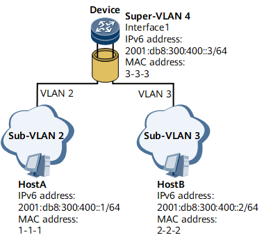
To address this problem, enable inter-VLAN proxy ND on Device's interface 1.
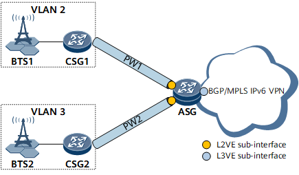
- CSG1 sends an NS packet to request for the MAC address of CSG2.
- Upon receipt of the NS packet, the ASG finds that the destination
IPv6 address in the packet is not its own IPv6 address and therefore
determines that the NS packet does not request for its MAC address.
The ASG then checks whether ND entries destined for CSG2 exist.
- If such ND entries exist and the VLAN information in the ND entries
is inconsistent with the VLAN information configured on the interface
receiving the NS packet, the ASG determines whether inter-VLAN proxy
ND is enabled on the associated VLAN interface.
If inter-VLAN proxy ND is enabled, the ASG sends the MAC address of the L3VE sub-interface to CSG1.
Upon receipt of the NA packet, CSG1 considers that this packet is sent by CSG2. CSG1 learns the MAC address of the ASG's L3VE sub-interface in the NA packet and sends data packets to CSG2 using this MAC address.
- If inter-VLAN proxy ND is not enabled, the NS packet is discarded.
- If such ND entries do not exist, the NS packet sent by CSG1 is
discarded and CSG2 checks whether inter-VLAN proxy ND is enabled on
the associated L3VE sub-interface.
- If inter-VLAN proxy ND is enabled, the NS packet is forwarded in VLAN 3 as a multicast packet and the destination IPv6 address of the NS packet is CSG2's IPv6 address. The corresponding ND entries are generated after the NA packet sent by CSG2 is received.
- If inter-VLAN proxy ND is not enabled, no action is required.
- If such ND entries exist and the VLAN information in the ND entries
is inconsistent with the VLAN information configured on the interface
receiving the NS packet, the ASG determines whether inter-VLAN proxy
ND is enabled on the associated VLAN interface.
Procedure
- Run system-view
The system view is displayed.
- Run interface interface-type interface-number
The interface view is displayed.
- Run ipv6 enable
IPv6 is enabled on the interface.
- Run ipv6 address { ipv6-address prefix-length | ipv6-address/prefix-length }
A global unicast address is configured for the interface.
- Run ipv6 nd
proxy inter-access-vlan enable
Inter-VLAN proxy ND is enabled.

The IPv6 address of the interface enabled with proxy ND must be on the same network segment as the IPv6 address of the host connected to the interface.
Proxy ND cannot be enabled on an interface configured with a CGA address. Otherwise, the replied NA packets that carry the CGA/RSA option may be discarded.
Multiple types of proxy ND can be configured in the interface view. The priorities of these proxy ND types are as follows in descending order: any proxy ND > intra-VLAN proxy ND/ inter-VLAN proxy ND/local proxy ND > routed proxy ND.
Inter-VLAN proxy ND is not supported for the devices that do not support configuration of VLAN segments.
- Proxy ND is not supported for the following types of packets:
- NS packets with a link-local address as the target address
- DAD NS packets with the source address of all 0s
- NS packets with the target address and interface address on different network segments
- NS packets with the IP address of the local host as the target address.
- Run commit
The configuration is committed.