Example for Configuring BFD for OSPF
This section describes how to configure BFD for OSPF. After BFD for OSPF is configured, BFD can fast detect link faults and report them to OSPF so that service traffic can be transmitted through the backup link.
Networking Requirements
OSPF enables the device to periodically send Hello packets to a neighboring device for fault detection. Detecting a fault takes more than 1s. With the development of technologies, voice, video, and other VOD services are widely used. These services are quite sensitive to packet loss and delays. When traffic is transmitted at gigabit rates, long-time fault detection will cause packet loss. This cannot meet high reliability requirements of the carrier-class network. BFD for OSPF is used to resolve the problem. After BFD for OSPF is configured, the link status can be rapidly detected and fault detection can be completed in milliseconds. This speeds up OSPF convergence when the link status changes.
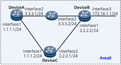
For example, as shown in Figure 1, the primary link Device A -> Device B and the secondary link Device A -> Device C -> Device B are deployed on the network. Traffic is transmitted on the primary link normally. When the primary link becomes faulty, the Device is expected to rapidly detect the fault and switch traffic to the secondary link.
You can configure BFD for OSPF to detect the OSPF neighbor relationship between Device A and Device B. When the link between Device A and Device B fails, BFD can rapidly detect the failure and report it to OSPF. Traffic is then switched to the secondary link.

Configuration Roadmap
The configuration roadmap is as follows:
Configure basic OSPF functions on each router for interconnection.
Enable global BFD.
Enable OSPF BFD on Device A and Device B.
Data Preparation
To complete the configuration, you need the following data:
Data of Device A, including the router ID (1.1.1.1), OSPF process number (1), and network segment addresses of Area 0 (3.3.3.0/24 and 1.1.1.0/24)
Data of Device B, including the router ID (2.2.2.2), OSPF process number (1), and network segment addresses of Area 0 (3.3.3.0/24, 2.2.2.0/24, and 172.16.1.0/24)
Data of Device C, including the router ID (3.3.3.3), OSPF process number (1), and network segment addresses of Area 0 (1.1.1.0/24 and 2.2.2.0/24)
Minimum interval at which BFD packets are received and sent and local detection multiplier on Device A and Device B
Procedure
- Assign an IP address to each interface. For configuration details, see Configuration Files in this section.
- Configure basic OSPF functions.
# Configure Device A.
[~DeviceA] router id 1.1.1.1
[~DeviceA] ospf 1
[*DeviceA-ospf-1] area 0
[*DeviceA-ospf-1-area-0.0.0.0] network 1.1.1.0 0.0.0.255
[*DeviceA-ospf-1-area-0.0.0.0] network 3.3.3.0 0.0.0.255
[*DeviceA-ospf-1-area-0.0.0.0] commit
[~DeviceA-ospf-1-area-0.0.0.0] quit
[~DeviceA-ospf-1] quit
# Configure Device B.
[~DeviceB] router id 2.2.2.2
[~DeviceB] ospf 1
[*DeviceB-ospf-1] area 0
[*DeviceB-ospf-1-area-0.0.0.0] network 2.2.2.0 0.0.0.255
[*DeviceB-ospf-1-area-0.0.0.0] network 3.3.3.0 0.0.0.255
[*DeviceB-ospf-1-area-0.0.0.0] network 172.16.1.0 0.0.0.255
[*DeviceB-ospf-1-area-0.0.0.0] commit
[~DeviceB-ospf-1-area-0.0.0.0] quit
[~DeviceB-ospf-1] quit
# Configure Device C.
[~DeviceC] router id 3.3.3.3
[~DeviceC] ospf 1
[*DeviceC-ospf-1] area 0
[*DeviceC-ospf-1-area-0.0.0.0] network 1.1.1.0 0.0.0.255
[*DeviceC-ospf-1-area-0.0.0.0] network 2.2.2.0 0.0.0.255
[*DeviceC-ospf-1-area-0.0.0.0] commit
[~DeviceC-ospf-1-area-0.0.0.0] quit
[~DeviceC-ospf-1] quit
# After the preceding configurations, run the display ospf peer command. You can view that a neighbor relationship is established between Device A and Device B, and between Device B and Device C. The following example uses the command output on Device A.
<DeviceA> display ospf peer
(M) Indicates MADJ interface
           OSPF Process 1 with Router ID 1.1.1.1
                 Neighbors

 Area 0.0.0.0 interface 3.3.3.1 ( GE0/1/8 )'s neighbors
 Router ID: 2.2.2.2         Address: 3.3.3.2
   State: Full  Mode:Nbr is  Master   Priority: 1
   DR: 3.3.3.1   BDR: 3.3.3.2    MTU: 0
   Dead timer due in  35  sec
   Retrans timer interval: 5
   Neighbor is up for 1h15m4s
   Neighbor up time : 2020-06-08 01:41:57
   Authentication Sequence: [ 0 ]

 Area 0.0.0.0 interface 1.1.1.1 ( GE0/1/0 )'s neighbors
 Router ID: 3.3.3.3         Address: 1.1.1.2
   State: Full  Mode:Nbr is  Master   Priority: 1
   DR: 1.1.1.1  BDR: 1.1.1.2  MTU: 0
   Dead timer due in  39  sec
   Retrans timer interval: 5
   Neighbor is up for 1h15m4s
   Neighbor up time : 2020-06-08 01:41:57
   Authentication Sequence: [ 0 ]
# Display information about the OSPF routing table on Device A, and you can view the routing entries to Device B and Device C. The next hop address of the route to 172.16.1.0/24 is 3.3.3.2, and service traffic is transmitted on the primary link (DeviceA → DeviceB).
<DeviceA> display ospf routing OSPF Process 1 with Router ID 1.1.1.1 Routing Tables Routing for Network Destination Cost Type NextHop AdvRouter Area 2.2.2.0/24 2 Stub 1.1.1.2 3.3.3.3 0.0.0.0 172.16.1.0/24 2 Stub 3.3.3.2 2.2.2.2 0.0.0.0 Total Nets: 2 Intra Area: 2 Inter Area: 0 ASE: 0 NSSA: 0 - Configure OSPF BFD.
# Enable global BFD on Device A.
[*DeviceA] bfd
[*DeviceA-bfd] quit
[*DeviceA] ospf 1
[*DeviceA-ospf-1] bfd all-interfaces enable
[*DeviceA-ospf-1] commit
[~DeviceA-ospf-1] quit
# Enable global BFD on Device B.
[*DeviceB] bfd
[*DeviceB-bfd] quit
[*DeviceB] ospf 1
[*DeviceB-ospf-1] bfd all-interfaces enable
[*DeviceB-ospf-1] commit
[~DeviceB-ospf-1] quit
# Enable global BFD on Device C.
[*DeviceC] bfd
[*DeviceC-bfd] quit
[*DeviceC] ospf 1
[*DeviceC-ospf-1] bfd all-interfaces enable
[*DeviceC-ospf-1] commit
[~DeviceC-ospf-1] quit
# After the preceding configurations, run the display ospf bfd session all command on Device A, Device B, or Device C. You can view that the BFD session is Up.
Use the command output Device A as an example.
[~DeviceA] display ospf bfd session all
          OSPF Process 1 with Router ID 1.1.1.1
  Area 0.0.0.0 interface 1.1.1.1(GE0/1/0)'s BFD Sessions

 NeighborId:2.2.2.2          AreaId:0.0.0.0          Interface:GE0/1/0
 BFDState:up                 rx    :1000             tx       :1000
 Multiplier:3                BFD Local Dis:0         LocalIpAdd:1.1.1.1
 RemoteIpAdd:1.1.1.2         Diagnostic Info:0

  Area 0.0.0.0 interface 3.3.3.1(GE0/1/8)'s BFD Sessions

 NeighborId:3.3.3.3          AreaId:0.0.0.0          Interface:GE0/1/8
 BFDState:up                 rx    :1000             tx       :1000
 Multiplier:3                BFD Local Dis:0         LocalIpAdd:3.3.3.1
 RemoteIpAdd:3.3.3.2         Diagnostic Info:0
- Configure BFD on an interface.
# Configure BFD on GigabitEthernet 0/1/8 of Device A. Set the minimum intervals at which packets are received and sent to 500 ms and the local detection multiplier to 4.
[~DeviceA] interface gigabitethernet 0/1/8
[*DeviceA-GigabitEthernet0/1/8] ospf bfd enable
[*DeviceA-GigabitEthernet0/1/8] ospf bfd min-tx-interval 500 min-rx-interval 500 detect-multiplier 4
[*DeviceA-GigabitEthernet0/1/8] commit
[~DeviceA-GigabitEthernet0/1/8] quit
# Configure BFD on GigabitEthernet 0/1/8 of Device B. Set the minimum intervals at which packets are received and sent to 500 ms and the local detection multiplier to 4.
[~DeviceB] interface gigabitethernet 0/1/8
[*DeviceB-GigabitEthernet0/1/8] ospf bfd enable
[*DeviceB-GigabitEthernet0/1/8] ospf bfd min-tx-interval 500 min-rx-interval 500 detect-multiplier 4
[*DeviceB-GigabitEthernet0/1/8] commit
[~DeviceB-GigabitEthernet0/1/8] quit
# After the preceding configurations, run the display ospf bfd session all command on Device A or Device B. You can check that the minimum intervals at which packets are sent and received are 500 ms and that the local detection multiplier is 4.
Use the command output Device B as an example.
[~DeviceB] display ospf bfd session all
          OSPF Process 1 with Router ID 2.2.2.2
  Area 0.0.0.0 interface 3.3.3.2(GE0/1/8)'s BFD Sessions

 NeighborId:1.1.1.1          AreaId:0.0.0.0          Interface: GigabitEthernet0/1/8
 BFDState:up                 rx    :500             tx       :500
 Multiplier:4                BFD Local Dis:0         LocalIpAdd:3.3.3.2
 RemoteIpAdd:3.3.3.1         Diagnostic Info:0

  Area 0.0.0.0 interface 2.2.2.2(GE0/1/0)'s BFD Sessions

 NeighborId:3.3.3.3          AreaId:0.0.0.0          Interface: GE0/1/0
 BFDState:up                 rx    :1000              tx       :1000
 Multiplier:3                BFD Local Dis:0         LocalIpAdd:2.2.2.2
 RemoteIpAdd:2.2.2.1         Diagnostic Info:0
- Verify the configuration.
# Run the shutdown command on GigabitEthernet 0/1/8 of Device B to simulate a primary link failure.
[~DeviceB] interface gigabitethernet 0/1/8
[*DeviceB-GigabitEthernet0/1/8] shutdown
# Display the routing table on Device A. You can view that the backup link (DeviceA - DeviceC - DeviceB) takes effect after the primary link fails and that the next hop address of the route to 172.16.1.0/24 is 1.1.1.2.
<DeviceA> display ospf routing
          OSPF Process 1 with Router ID 1.1.1.1
                   Routing Tables

 Routing for Network
 Destination        Cost       Type       NextHop         AdvRouter       Area
 2.2.2.0/24         2          Stub       1.1.1.2         3.3.3.3         0.0.0.0
 172.16.1.0/24    3         Stub      1.1.1.2       2.2.2.2       0.0.0.0

 Total Nets: 2
 Intra Area: 2  Inter Area: 0  ASE: 0  NSSA: 0
Configuration Files
Device A configuration file
#
 sysname DeviceA
#
 router id 1.1.1.1
#
 bfd
#
interface GigabitEthernet0/1/0
 undo shutdown
 ip address 1.1.1.1 255.255.255.0
#
interface GigabitEthernet0/1/8
 undo shutdown
 ip address 3.3.3.1 255.255.255.0
 ospf bfd enable
 ospf bfd min-tx-interval 500 min-rx-interval 500 detect-multiplier 4
#
ospf 1
 bfd all-interfaces enable
 area 0.0.0.0
  network 3.3.3.0 0.0.0.255
  network 1.1.1.0 0.0.0.255
#
return
Device B configuration file
#
 sysname DeviceB
#
 router id 2.2.2.2
#
 bfd
#
 interface GigabitEthernet0/1/0
 undo shutdown
 ip address 2.2.2.2 255.255.255.0
#
interface GigabitEthernet0/1/8
 undo shutdown
 ip address 3.3.3.2 255.255.255.0
 ospf bfd enable
 ospf bfd min-tx-interval 500 min-rx-interval 500 detect-multiplier 4
#
interface GigabitEthernet0/1/16
 undo shutdown
 ip address 172.16.1.1 255.255.255.0
#
ospf 1
 bfd all-interfaces enable
 area 0.0.0.0
  network 3.3.3.0 0.0.0.255
  network 2.2.2.0 0.0.0.255
  network 172.16.1.0 0.0.0.255
#
return
Device C configuration file
#
 sysname DeviceC
#
 router id 3.3.3.3
#
 bfd
#
 interface GigabitEthernet0/1/0
 undo shutdown
 ip address 1.1.1.2 255.255.255.0
#
interface GigabitEthernet0/1/8
 undo shutdown
 ip address 2.2.2.1 255.255.255.0
 ospf bfd enable
#
ospf 1
 bfd all-interfaces enable
 area 0.0.0.0
  network 1.1.1.0 0.0.0.255
  network 2.2.2.0 0.0.0.255
#
return