Example for Configuring an OSPF Sham Link
This section provides an example for configuring an OSPF sham link so that traffic between sites of the same VPN in the same OSPF area is forwarded through the OSPF intra-area route over the BGP/MPLS IP VPN backbone network.
Networking Requirements
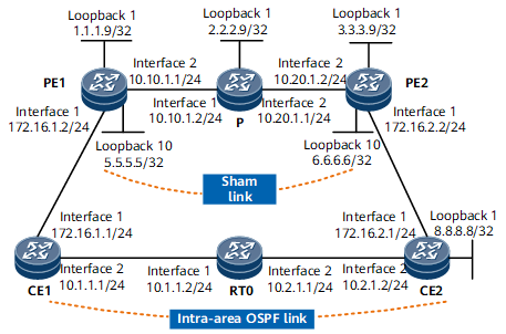
In Figure 1, CE1 and CE2 reside in the same OSPF area, belong to VPN1, and are connected to PE1 and PE2, respectively. In this example, the cost of each link is 1.
It is required that OSPF run between each CE and its connected PE and the VPN traffic between CE1 and CE2 be forwarded over the MPLS backbone network.
Configuration Roadmap
The configuration roadmap is as follows:
Configure an MP-IBGP peer relationship between PEs and configure OSPF between each CE and its connected PE.
Create a VPN instance on each PE and bind the VPN instance to the interface connected to the corresponding CE.
Create an OSPF sham link between PEs.
Adjust the cost of forwarding interfaces over the user network to ensure that the cost of the OSPF route used to forward the traffic over the user network is greater than that of the sham link.
Data Preparation
To complete the configuration, you need the following data:
MPLS LSR IDs of the PEs and P
VPN instance name, RD, and VPN target of each PE
Data used to configure OSPF (The OSPF process running on the backbone network, the OSPF process running on the user network, and the OSPF process connecting each PE to the corresponding CE are different.)
Cost of the sham link and the cost of the OSPF route used to forward the traffic over the user network
Procedure
- Configure OSPF on the user network.
Configure OSPF on CE1, RT0, and CE2 and advertise network segments of their interfaces.
# Configure CE1.
<HUAWEI> system-view
[~HUAWEI] sysname CE1
[~CE1] interface GigabitEthernet0/1/8
[~CE1-GigabitEthernet0/1/8] ip address 10.1.1.1 24
[*CE1-GigabitEthernet0/1/8] quit
[*CE1] interface GigabitEthernet0/1/0
[*CE1-GigabitEthernet0/1/0] ip address 172.16.1.1 24
[*CE1-GigabitEthernet0/1/0] quit
[*CE1] ospf
[*CE1-ospf-1] area 0
[*CE1-ospf-1-area-0.0.0.0] network 10.1.1.0 0.0.0.255
[*CE1-ospf-1-area-0.0.0.0] network 172.16.1.0 0.0.0.255
[*CE1-ospf-1-area-0.0.0.0] quit
[*CE1-ospf-1] quit
[*CE1] commit
# Configure RT0.
<HUAWEI> system-view
[~HUAWEI] sysname RT0
[~RT0] interface GigabitEthernet0/1/0
[~RT0-GigabitEthernet0/1/0] ip address 10.1.1.2 24
[*RT0-GigabitEthernet0/1/0] quit
[*RT0] interface GigabitEthernet0/1/8
[*RT0-GigabitEthernet0/1/8] ip address 10.2.1.1 24
[*RT0-GigabitEthernet0/1/8] quit
[*RT0] ospf
[*RT0-ospf-1] area 0
[*RT0-ospf-1-area-0.0.0.0] network 10.1.1.0 0.0.0.255
[*RT0-ospf-1-area-0.0.0.0] network 10.2.1.0 0.0.0.255
[*RT0-ospf-1-area-0.0.0.0] quit
[*RT0-ospf-1] quit
[*RT0] commit
# Configure CE2.
<HUAWEI> system-view
[~HUAWEI] sysname CE2
[~CE2] interface GigabitEthernet0/1/8
[~CE2-GigabitEthernet0/1/8] ip address 10.2.1.2 24
[*CE2-GigabitEthernet0/1/8] quit
[*CE2] interface GigabitEthernet0/1/0
[*CE2-GigabitEthernet0/1/0] ip address 172.16.2.1 24
[*CE2-GigabitEthernet0/1/0] quit
[*CE2] ospf
[*CE2-ospf-1] area 0
[*CE2-ospf-1-area-0.0.0.0] network 10.2.1.0 0.0.0.255
[*CE2-ospf-1-area-0.0.0.0] network 172.16.2.0 0.0.0.255
[*CE2-ospf-1-area-0.0.0.0] quit
[*CE2-ospf-1] quit
[*CE2] commit
- Configure basic BGP/MPLS IP VPN functions on the backbone network, including an IGP (OSPF) on the backbone network, MPLS and LDP on the backbone network, and an MP-IBGP peer relationship between PEs.
# Configure PE1.
<HUAWEI> system-view
[~HUAWEI] sysname PE1
[~PE1] interface loopback 1
[~PE1-LoopBack1] ip address 1.1.1.9 32
[*PE1-LoopBack1] quit
[*PE1] mpls lsr-id 1.1.1.9
[*PE1] mpls
[*PE1-mpls] quit
[*PE1] mpls ldp
[*PE1-mpls-ldp] quit
[*PE1] interface GigabitEthernet0/1/8
[*PE1-GigabitEthernet0/1/8] ip address 10.10.1.1 24
[*PE1-GigabitEthernet0/1/8] mpls
[*PE1-GigabitEthernet0/1/8] mpls ldp
[*PE1-GigabitEthernet0/1/8] quit
[*PE1] ospf
[*PE1-ospf-1] area 0
[*PE1-ospf-1-area-0.0.0.0] network 1.1.1.9 0.0.0.0
[*PE1-ospf-1-area-0.0.0.0] network 10.10.1.0 0.0.0.255
[*PE1-ospf-1-area-0.0.0.0] quit
[*PE1-ospf-1] quit
[*PE1] bgp 100
[*PE1-bgp] peer 3.3.3.9 as-number 100
[*PE1-bgp] peer 3.3.3.9 connect-interface loopback 1
[*PE1-bgp] ipv4-family vpnv4
[*PE1-bgp-af-vpnv4] peer 3.3.3.9 enable
[*PE1-bgp-af-vpnv4] quit
[*PE1-bgp] quit
[*PE1] commit
# Configure the P.
<HUAWEI> system-view
[~HUAWEI] sysname P
[~P] interface loopback 1
[~P-LoopBack1] ip address 2.2.2.9 32
[*P-LoopBack1] quit
[*P] mpls lsr-id 2.2.2.9
[*P] mpls
[*P-mpls] quit
[*P] mpls ldp
[*P-mpls-ldp] quit
[*P] interface GigabitEthernet0/1/0
[*P-GigabitEthernet0/1/0] ip address 10.10.1.2 24
[*P-GigabitEthernet0/1/0] mpls
[*P-GigabitEthernet0/1/0] mpls ldp
[*P-GigabitEthernet0/1/0] quit
[*P] interface GigabitEthernet0/1/8
[*P-GigabitEthernet0/1/8] ip address 10.20.1.1 24
[*P-GigabitEthernet0/1/8] mpls
[*P-GigabitEthernet0/1/8] mpls ldp
[*P-GigabitEthernet0/1/8] quit
[*P] ospf
[*P-ospf-1] area 0
[*P-ospf-1-area-0.0.0.0] network 2.2.2.9 0.0.0.0
[*P-ospf-1-area-0.0.0.0] network 10.10.1.0 0.0.0.255
[*P-ospf-1-area-0.0.0.0] network 10.20.1.0 0.0.0.255
[*P-ospf-1-area-0.0.0.0] quit
[*P-ospf-1] quit
[*P] commit
# Configure PE2.
<HUAWEI> system-view
[~HUAWEI] sysname PE2
[~PE2] interface loopback 1
[~PE2-LoopBack1] ip address 3.3.3.9 32
[*PE2-LoopBack1] quit
[*PE2] mpls lsr-id 3.3.3.9
[*PE2] mpls
[*PE2-mpls] quit
[*PE2] mpls ldp
[*PE2-mpls-ldp] quit
[*PE2] interface GigabitEthernet0/1/8
[*PE2-GigabitEthernet0/1/8] ip address 10.20.1.2 24
[*PE2-GigabitEthernet0/1/8] mpls
[*PE2-GigabitEthernet0/1/8] mpls ldp
[*PE2-GigabitEthernet0/1/8] quit
[*PE2] ospf
[*PE2-ospf-1] area 0
[*PE2-ospf-1-area-0.0.0.0] network 3.3.3.9 0.0.0.0
[*PE2-ospf-1-area-0.0.0.0] network 10.20.1.0 0.0.0.255
[*PE2-ospf-1-area-0.0.0.0] quit
[*PE2-ospf-1] quit
[*PE2] bgp 100
[*PE2-bgp] peer 1.1.1.9 as-number 100
[*PE2-bgp] peer 1.1.1.9 connect-interface loopback 1
[*PE2-bgp] ipv4-family vpnv4
[*PE2-bgp-af-vpnv4] peer 1.1.1.9 enable
[*PE2-bgp-af-vpnv4] quit
[*PE2-bgp] quit
[*PE2] commit
After completing the configurations, PE1 and PE2 learn the route to each other's loopback interface and establish an MP-IBGP peer relationship.
- Configure the connection between each PE and the corresponding CE, with OSPF running between them.
# Configure PE1.
[~PE1] ip vpn-instance vpn1
[*PE1-vpn-instance-vpn1] ipv4-family
[*PE1-vpn-instance-vpn1-af-ipv4] route-distinguisher 100:1
[*PE1-vpn-instance-vpn1-af-ipv4] vpn-target 1:1
[*PE1-vpn-instance-vpn1-af-ipv4] quit
[*PE1-vpn-instance-vpn1] quit
[*PE1] interface gigabitethernet 0/1/0
[*PE1-GigabitEthernet0/1/0] ip binding vpn-instance vpn1
[*PE1-GigabitEthernet0/1/0] ip address 172.16.1.2 24
[*PE1-GigabitEthernet0/1/0] quit
[*PE1] ospf 100 vpn-instance vpn1
[*PE1-ospf-100] domain-id 10
[*PE1-ospf-100] import-route bgp
[*PE1-ospf-100] area 0
[*PE1-ospf-100-area-0.0.0.0] network 172.16.1.0 0.0.0.255
[*PE1-ospf-100-area-0.0.0.0] quit
[*PE1-ospf-100] quit
[*PE1] bgp 100
[*PE1-bgp] ipv4-family vpn-instance vpn1
[*PE1-bgp-vpn1] import-route direct
[*PE1-bgp-vpn1] import-route ospf 100
[*PE1-bgp-vpn1] quit
[*PE1-bgp] quit
[*PE1] commit
# Configure PE2.
[~PE2] ip vpn-instance vpn1
[*PE2-vpn-instance-vpn1] ipv4-family
[*PE2-vpn-instance-vpn1-af-ipv4] route-distinguisher 100:2
[*PE2-vpn-instance-vpn1-af-ipv4] vpn-target 1:1
[*PE2-vpn-instance-vpn1-af-ipv4] quit
[*PE2-vpn-instance-vpn1] quit
[*PE2] interface GigabitEthernet0/1/0
[*PE2-GigabitEthernet0/1/0] ip binding vpn-instance vpn1
[*PE2-GigabitEthernet0/1/0] ip address 172.16.2.2 24
[*PE2-GigabitEthernet0/1/0] quit
[*PE2] ospf 100 vpn-instance vpn1
[*PE2-ospf-100] import-route bgp
[*PE2-ospf-100] domain-id 10
[*PE2-ospf-100] area 0
[*PE2-ospf-100-area-0.0.0.0] network 172.16.2.0 0.0.0.255
[*PE2-ospf-100-area-0.0.0.0] quit
[*PE2-ospf-100] quit
[*PE2] bgp 100
[*PE2-bgp] ipv4-family vpn-instance vpn1
[*PE2-bgp-vpn1] import-route direct
[*PE2-bgp-vpn1] import-route ospf 100
[*PE2-bgp-vpn1] quit
[*PE2-bgp] quit
[*PE2] commit
After completing the configurations, run the display ip routing-table vpn-instance command on a PE. You may find that the route to the remote CE is an OSPF route over the user network rather than the BGP route over the backbone network.
The following example uses the command output on PE1.
<PE1> display ip routing-table vpn-instance vpn1
Route Flags: R - relay, D - download to fib, T - to vpn-instance, B - black hole route
------------------------------------------------------------------------------
Routing Table: vpn1
         Destinations : 5        Routes : 5
Destination/Mask  Proto  Pre  Cost         Flags  NextHop       Interface
     10.1.1.0/24  OSPF   10   2                D  172.16.1.1    GigabitEthernet0/1/0
     10.2.1.0/24  OSPF   10   3                D  172.16.1.1    GigabitEthernet0/1/0
    172.16.1.0/24 Direct 0    0                D  172.16.1.2    GigabitEthernet0/1/0
    172.16.1.2/32 Direct 0    0                D  127.0.0.1     GigabitEthernet0/1/0
    172.16.2.0/24 OSPF   10   4                D  172.16.1.1    GigabitEthernet0/1/0
- Configure a sham link.

To ensure that VPN traffic is forwarded over the MPLS backbone network, ensure that the cost of the sham link is smaller than that of the OSPF route used to forward the traffic over the user network when configuring the sham link. In most cases, you need to change the cost of the interfaces on the user network to ensure that the cost of the OSPF route used to forward the traffic over the user network is greater than that of the sham link.
# Configure CE1.
[~CE1] interface GigabitEthernet0/1/8
[~CE1-GigabitEthernet0/1/8] ospf cost 10
# Configure CE2.
[~CE2] interface GigabitEthernet0/1/8
[~CE2-GigabitEthernet0/1/8] ospf cost 10
[~CE2] interface loopback 1
[~CE2-LoopBack1] ip address 8.8.8.8 32
[*CE2-LoopBack1] ospf enable 1 area 0
[*CE2-LoopBack1] quit
[*CE2] commit
# Configure PE1.
[~PE1] interface loopback 10
[*PE1-LoopBack10] ip binding vpn-instance vpn1
[*PE1-LoopBack10] ip address 5.5.5.5 32
[*PE1-LoopBack10] quit
[*PE1] ospf 100 router-id 11.11.11.11
[*PE1-ospf-100] area 0
[*PE1-ospf-100-area-0.0.0.0] sham-link 5.5.5.5 6.6.6.6 cost 1
[*PE1-ospf-100-area-0.0.0.0] quit
[*PE1-ospf-100] quit
[*PE1] commit
# Configure PE2.
[~PE2] interface loopback 10
[*PE2-LoopBack10] ip binding vpn-instance vpn1
[*PE2-LoopBack10] ip address 6.6.6.6 32
[*PE2-LoopBack10] quit
[*PE2] ospf 100 router-id 22.22.22.22
[*PE2-ospf-100] area 0
[*PE2-ospf-100-area-0.0.0.0] sham-link 6.6.6.6 5.5.5.5 cost 1
[*PE2-ospf-100-area-0.0.0.0] quit
[*PE2-ospf-100] quit
[*PE2] commit
- Verify the configuration.
After completing the configurations, run the display ip routing-table vpn-instance command again on the PE. You may find that the route to the remote CE becomes the BGP route over the backbone network and a route to the destination IP address of the sham link also exist in the routing table.
The following example uses the command output on PE1.
<PE1> display ip routing-table vpn-instance vpn1
Route Flags: R - relay, D - download to fib, T - to vpn-instance, B - black hole route
------------------------------------------------------------------------------
 Routing Table: vpn1
         Destinations : 10        Routes : 10
 Destination/Mask  Proto  Pre  Cost      Flags  NextHop           Interface
       5.5.5.5/32  Direct 0    0            D   127.0.0.1         LoopBack10
       6.6.6.6/32  IBGP   255  0            RD  3.3.3.9           GigabitEthernet0/1/8
       8.8.8.8/32  IBGP   255  2            RD  3.3.3.9           GigabitEthernet0/1/8
      10.1.1.0/24  OSPF   10   11           D   172.16.1.1        GigabitEthernet0/1/0
      10.2.1.0/24  OSPF   10   12           D   172.16.1.1        GigabitEthernet0/1/0
     172.16.1.0/24 Direct 0    0            D   172.16.1.2        GigabitEthernet0/1/0
     172.16.1.2/32 Direct 0    0            D   127.0.0.1         GigabitEthernet0/1/0
   172.16.1.255/32 Direct 0    0            D   127.0.0.1         GigabitEthernet0/1/0
     172.16.2.0/24 IBGP   255  0            RD  3.3.3.9           GigabitEthernet0/1/8
255.255.255.255/32 Direct 0    0            D   127.0.0.1         InLoopBack0
Run the display ip routing-table command on a CE. You may find that the cost of the OSPF route to the remote CE becomes 3 and the next hop is the IP address of the connected PE interface. The next hop indicates that the VPN traffic to the remote end is forwarded over the backbone network.
The following example uses the command output on CE1.
<CE1> display ip routing-table
Route Flags: R - relay, D - download to fib, T - to vpn-instance, B - black hole route
------------------------------------------------------------------------------
Routing Table : _public_
         Destinations : 15       Routes : 15
Destination/Mask    Proto   Pre  Cost        Flags NextHop         Interface
        5.5.5.5/32  O_ASE   150  1             D   172.16.1.2      GigabitEthernet0/1/0
        6.6.6.6/32  O_ASE   150  1             D   172.16.1.2      GigabitEthernet0/1/0
        8.8.8.8/32  OSPF    10   3             D   172.16.1.2      GigabitEthernet0/1/0
       10.1.1.0/24  Direct  0    0             D   10.1.1.1        GigabitEthernet0/1/8
       10.1.1.1/32  Direct  0    0             D   127.0.0.1       GigabitEthernet0/1/8
     10.1.1.255/32  Direct  0    0             D   127.0.0.1       GigabitEthernet0/1/8
       10.2.1.0/24  OSPF    10   11            D   10.1.1.2        GigabitEthernet0/1/8
      127.0.0.0/8   Direct  0    0             D   127.0.0.1       InLoopBack0
      127.0.0.1/32  Direct  0    0             D   127.0.0.1       InLoopBack0
127.255.255.255/32  Direct  0    0             D   127.0.0.1       InLoopBack0
     172.16.1.0/24  Direct  0    0             D   172.16.1.1      GigabitEthernet0/1/0
     172.16.1.1/32  Direct  0    0             D   127.0.0.1       GigabitEthernet0/1/0
   172.16.1.255/32  Direct  0    0             D   127.0.0.1       GigabitEthernet0/1/0
     172.16.2.0/24  OSPF    10   3             D   172.16.1.2      GigabitEthernet0/1/0
255.255.255.255/32  Direct  0    0             D   127.0.0.1       InLoopBack0
Cost (3) of the OSPF route from CE1 to CE2 = Cost (1) of the link from CE1 to PE1 + Cost (1) of the sham link + Cost (1) of the link from PE2 to CE2
Run the tracert command and you may find that the next hop for CE1 to send data to CE2 is the IP address of PE1's GE 0/1/0. The next hop indicates that the VPN traffic to the remote end is forwarded over the backbone network.
<CE1> tracert 172.16.2.1
 traceroute to 172.16.2.1(172.16.2.1), max hops: 30 ,packet length: 40,press CTRL_C to break
 1 172.16.1.2 131 ms  2 ms  1 ms
 2 10.10.1.2 475 ms  4 ms  4 ms
 3 172.16.2.2 150 ms  3 ms  4 ms
 4 172.16.2.1 76 ms  3 ms  5 ms
<CE1> tracert 10.2.1.2
 traceroute to 10.2.1.2(10.2.1.2), max hops: 30 ,packet length: 40,press CTRL_C to break
 1 10.1.1.2 60 ms  1 ms  1 ms
 2 10.2.1.2 12 ms  2 ms  2 ms
Run the display ospf sham-link command on a PE to check whether the sham link is established.
The following example uses the command output on PE1.
<PE1> display ospf sham-link
          OSPF Process 100 with Router ID 11.11.11.11
 Area         NeighborId        Source-IP       Destination-IP  State Cost
 0.0.0.0      22.22.22.22       5.5.5.5         6.6.6.6         P-2-P  1
Run the display ospf sham-link area command. The following command output shows that the OSPF neighbor relationship is in Full state.
<PE1> display ospf sham-link area 0
          OSPF Process 100 with Router ID 11.11.11.11
  Sham-Link: 5.5.5.5 --> 6.6.6.6
  NeighborID: 22.22.22.22,   State: Full,    GR status: Normal
  Area: 0.0.0.0
  Cost: 1 , State: P-2-P , Type: Sham
  Timers: Hello 10 , Dead 40 , Retransmit 5 , Transmit Delay 1
Run the display ospf routing command on a CE. The following command output shows that the route to the remote CE is an intra-area route.
<CE1> display ospf routing
          OSPF Process 1 with Router ID 10.1.1.1
                   Routing Tables
 Routing for Network
 Destination        Cost  Type       NextHop         AdvRouter       Area
 8.8.8.8/32         3     Stub       172.16.1.2      10.2.1.2        0.0.0.0
 10.1.1.0/24        10    Direct     10.1.1.1        10.1.1.1        0.0.0.0
 10.2.1.0/24        11    Transit    10.1.1.2        10.1.1.2        0.0.0.0
 172.16.1.0/24      1     Direct     172.16.1.1      10.1.1.1        0.0.0.0
 172.16.2.0/24      3     Transit    172.16.1.2      10.2.1.2        0.0.0.0
 Routing for ASEs
 Destination        Cost      Type       Tag         NextHop         AdvRouter
 6.6.6.6/32         1         Type2      3489661028  172.16.1.2      11.11.11.11
 5.5.5.5/32         1         Type2      3489661028  172.16.1.2      22.22.22.22
 Total Nets: 7
 Intra Area: 5  Inter Area: 0  ASE: 2  NSSA: 0
Configuration Files
PE1 configuration file
#
 sysname PE1
#
ip vpn-instance vpn1
 ipv4-family
  route-distinguisher 100:1
  apply-label per-instance
  vpn-target 1:1 export-extcommunity
  vpn-target 1:1 import-extcommunity
#
 mpls lsr-id 1.1.1.9
 mpls
#
mpls ldp
#
interface GigabitEthernet0/1/0
 undo shutdown
 ip binding vpn-instance vpn1
 ip address 172.16.1.2 255.255.255.0
#
interface GigabitEthernet0/1/8
 undo shutdown
 ip address 10.10.1.1 255.255.255.0
 mpls
 mpls ldp
#
interface LoopBack1
 ip address 1.1.1.9 255.255.255.255
#
interface LoopBack10
 ip binding vpn-instance vpn1
 ip address 5.5.5.5 255.255.255.255
#
bgp 100
 peer 3.3.3.9 as-number 100
 peer 3.3.3.9 connect-interface LoopBack1
 #
 ipv4-family unicast
  undo synchronization
  peer 3.3.3.9 enable
 #
 ipv4-family vpnv4
  policy vpn-target
  peer 3.3.3.9 enable
  #
 ipv4-family vpn-instance vpn1
  import-route direct
  import-route ospf 100
#
ospf 1
 area 0.0.0.0
  network 1.1.1.9 0.0.0.0
  network 10.10.1.0 0.0.0.255
#
ospf 100 router-id 11.11.11.11 vpn-instance vpn1
 import-route bgp
 domain-id 0.0.0.10
 area 0.0.0.0
  network 172.16.1.0 0.0.0.255
  sham-link 5.5.5.5 6.6.6.6 cost 1
#
return
P configuration file
#
 sysname P
#
 mpls lsr-id 2.2.2.9
 mpls
#
mpls ldp
#
interface GigabitEthernet0/1/0
 undo shutdown
 ip address 10.10.1.2 255.255.255.0
 mpls
 mpls ldp
#
interface GigabitEthernet0/1/8
 undo shutdown
 ip address 10.20.1.1 255.255.255.0
 mpls
 mpls ldp
#
interface LoopBack1
 ip address 2.2.2.9 255.255.255.255
#
ospf 1
 area 0.0.0.0
  network 2.2.2.9 0.0.0.0
  network 10.10.1.0 0.0.0.255
  network 10.20.1.0 0.0.0.255
#
return
PE2 configuration file
#
 sysname PE2
#
ip vpn-instance vpn1
 ipv4-family
  route-distinguisher 100:2
  apply-label per-instance
  vpn-target 1:1 export-extcommunity
  vpn-target 1:1 import-extcommunity
#
 mpls lsr-id 3.3.3.9
 mpls
#
mpls ldp
#
interface GigabitEthernet0/1/0
 undo shutdown
 ip binding vpn-instance vpn1
 ip address 172.16.2.2 255.255.255.0
#
interface GigabitEthernet0/1/8
 undo shutdown
 ip address 10.20.1.2 255.255.255.0
 mpls
 mpls ldp
#
interface LoopBack1
 ip address 3.3.3.9 255.255.255.255
#
interface LoopBack10
 ip binding vpn-instance vpn1
 ip address 6.6.6.6 255.255.255.255
#
bgp 100
 peer 1.1.1.9 as-number 100
 peer 1.1.1.9 connect-interface LoopBack1
 #
 ipv4-family unicast
  undo synchronization
  peer 1.1.1.9 enable
 #
 ipv4-family vpnv4
  policy vpn-target
  peer 1.1.1.9 enable
#
 ipv4-family vpn-instance vpn1
  import-route direct
  import-route ospf 100
#
ospf 1
 area 0.0.0.0
  network 3.3.3.9 0.0.0.0
  network 10.20.1.0 0.0.0.255
#
ospf 100 router-id 22.22.22.22 vpn-instance vpn1
 import-route bgp
 domain-id 0.0.0.10
 area 0.0.0.0
  network 172.16.2.0 0.0.0.255
  sham-link 6.6.6.6 5.5.5.5 cost 1
#
return
CE1 configuration file
#
 sysname CE1
#
interface GigabitEthernet0/1/0
 undo shutdown
 ip address 172.16.1.1 255.255.255.0
#
interface GigabitEthernet0/1/8
 undo shutdown
 ip address 10.1.1.1 255.255.255.0
 ospf cost 10
#
interface LoopBack0
 ip address 8.8.8.8 255.255.255.255
 ospf enable 1 area 0.0.0.0
#
ospf 1
 area 0.0.0.0
  network 172.16.1.0 0.0.0.255
  network 10.1.1.0 0.0.0.255
#
return
CE2 configuration file
#
 sysname CE2
#
interface GigabitEthernet0/1/0
 undo shutdown
 ip address 172.16.2.1 255.255.255.0
#
interface GigabitEthernet0/1/8
 undo shutdown
 ip address 10.2.1.2 255.255.255.0
 ospf cost 10
#
ospf 1
 area 0.0.0.0
  network 10.2.1.0 0.0.0.255
  network 172.16.2.0 0.0.0.255
#
return
RT0 configuration file
#
 sysname RT0
#
interface GigabitEthernet0/1/0
 undo shutdown
 ip address 10.1.1.2 255.255.255.0
#
interface GigabitEthernet0/1/8
 undo shutdown
 ip address 10.2.1.1 255.255.255.0
#
ospf 1
 area 0.0.0.0
  network 10.1.1.0 0.0.0.255
  network 10.2.1.0 0.0.0.255
#
return