Example for Configuring OSPF Multi-Area Adjacency
This section provides an example for configuring OSPF multi-area adjacency, which includes configuration of enabling OSPF on each device, physical interface, and OSPF multi-area adjacency interface.
Networking Requirements
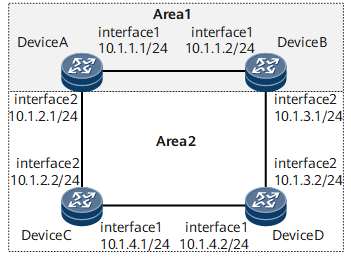
In Figure 1, all routers run OSPF, and the AS consists of two areas: area 1 and area 2. The link between DeviceA and DeviceB in area 1 is a high-speed link. Because intra-area links take precedence over inter-area links during OSPF route selection, traffic from DeviceA to DeviceB in area 2 is forwarded along the low-speed link of DeviceA->DeviceC->DeviceD->DeviceB, even though high-speed link between DeviceA and DeviceB exists. It is required that traffic from DeviceA to DeviceB in area 2 be forwarded along the high-speed link between DeviceA and DeviceB. In this case, configure OSPF multi-area adjacency on DeviceA and DeviceB and add their multi-area adjacency interfaces to area 2.

Configuration Roadmap
The configuration roadmap is as follows:
Enable OSPF on each router.
Enable OSPF on physical interfaces.
Enable OSPF on multi-area adjacency interfaces.
Data Preparation
- OSPF process ID: 1
- OSPF areas: area 1 and area 2
Procedure
- Configure an IP address for each interface. The configuration details are not provided here.
- Configure basic OSPF functions.
# Configure Device A.
[~DeviceA] ospf 1
[*DeviceA-ospf-1] area 1
[*DeviceA-ospf-1-area-0.0.0.1] quit
[*DeviceA-ospf-1] quit
[*DeviceA] interface gigabitethernet 0/1/0
[*DeviceA-GigabitEthernet0/1/0] ospf enable 1 area 1
[*DeviceA-GigabitEthernet0/1/0] quit
[*DeviceA] ospf 1
[*DeviceA-ospf-1] area 2
[*DeviceA-ospf-1-area-0.0.0.2] quit
[*DeviceA-ospf-1] quit
[*DeviceA] interface gigabitethernet 0/1/8
[*DeviceA-GigabitEthernet0/1/8] ospf enable 1 area 2
[*DeviceA-GigabitEthernet0/1/8] quit
[*DeviceA] commit
# Configure Device B.
[~DeviceB] ospf 1
[*DeviceB-ospf-1] area 1
[*DeviceB-ospf-1-area-0.0.0.1] quit
[*DeviceB-ospf-1] quit
[*DeviceB] interface gigabitethernet 0/1/0
[*DeviceB-GigabitEthernet0/1/0] ospf enable 1 area 1
[*DeviceB-GigabitEthernet0/1/0] quit
[*DeviceB] ospf 1
[*DeviceB-ospf-1] area 2
[*DeviceB-ospf-1-area-0.0.0.2] quit
[*DeviceB-ospf-1] quit
[*DeviceB] interface gigabitethernet 0/1/8
[*DeviceB-GigabitEthernet0/1/8] ospf enable 1 area 2
[*DeviceB-GigabitEthernet0/1/8] quit
[*DeviceB] commit
# Configure Device C.
[~DeviceC] ospf 1
[*DeviceC-ospf-1] area 2
[*DeviceC-ospf-1-area-0.0.0.2] quit
[*DeviceC-ospf-1] quit
[*DeviceC] interface gigabitethernet 0/1/0
[*DeviceC-GigabitEthernet0/1/0] ospf enable 1 area 2
[*DeviceC-GigabitEthernet0/1/0] quit
[*DeviceC] interface gigabitethernet 0/1/8
[*DeviceC-GigabitEthernet0/1/8] ospf enable 1 area 2
[*DeviceC-GigabitEthernet0/1/8] quit
[*DeviceC] commit
# Configure Device D.
[~DeviceD] ospf 1
[*DeviceD-ospf-1] area 2
[*DeviceD-ospf-1-area-0.0.0.2] quit
[*DeviceD-ospf-1] quit
[*DeviceD] interface gigabitethernet 0/1/0
[*DeviceD-GigabitEthernet0/1/0] ospf enable 1 area 2
[*DeviceD-GigabitEthernet0/1/0] quit
[*DeviceD] interface gigabitethernet 0/1/8
[*DeviceD-GigabitEthernet0/1/8] ospf enable 1 area 2
[*DeviceD-GigabitEthernet0/1/8] quit
[*DeviceD] commit
# Run the display ospf peer brief command to check brief information about OSPF neighbors. DeviceA is used as an example. The following command output shows that the OSPF neighbor relationships between DeviceA and DeviceB and between DeviceA and DeviceC are established.
[~DeviceA] display ospf peer brief
(M) Indicates MADJ neighbor


          OSPF Process 1 with Router ID 1.1.1.1
                   Peer Statistic Information
Total number of peer(s): 2
 Peer(s) in full state: 2
-----------------------------------------------------------------------------
 Area Id         Interface                  Neighbor id          State
 0.0.0.1         GigabitEthernet0/1/0       10.1.1.2             Full
 0.0.0.2         GigabitEthernet0/1/8       10.1.1.1             Full
-----------------------------------------------------------------------------
# Run the display ip routing-table command to check information about the IP routing table. DeviceA is used as an example. The following command output shows that the outbound interface of the route destined for 1.1.1.1 is GigabitEthernet 0/1/8.
[~DeviceA] display ip routing-table
Route Flags: R - relay, D - download to fib, T - to vpn-instance, B - black hole route
------------------------------------------------------------------------------
Routing Table : _public_
         Destinations : 13       Routes : 13

Destination/Mask    Proto   Pre  Cost        Flags NextHop         Interface

        1.1.1.1/32  OSPF    10   3             D   10.1.2.2        GigabitEthernet0/1/8
       10.1.1.0/24  Direct  0    0             D   10.1.1.1        GigabitEthernet0/1/0
       10.1.1.1/32  Direct  0    0             D   127.0.0.1       GigabitEthernet0/1/0
     10.1.1.255/32  Direct  0    0             D   127.0.0.1       GigabitEthernet0/1/0
       10.1.2.0/24  Direct  0    0             D   10.1.2.1        GigabitEthernet0/1/8
       10.1.2.1/32  Direct  0    0             D   127.0.0.1       GigabitEthernet0/1/8
     10.1.2.255/32  Direct  0    0             D   127.0.0.1       GigabitEthernet0/1/8
       10.1.3.0/24  OSPF    10   3             D   10.1.2.2        GigabitEthernet0/1/8
       10.1.4.0/24  OSPF    10   2             D   10.1.2.2        GigabitEthernet0/1/8
      127.0.0.0/8   Direct  0    0             D   127.0.0.1       InLoopBack0
      127.0.0.1/32  Direct  0    0             D   127.0.0.1       InLoopBack0
127.255.255.255/32  Direct  0    0             D   127.0.0.1       InLoopBack0
255.255.255.255/32  Direct  0    0             D   127.0.0.1       InLoopBack0
The preceding command output shows that traffic from router A to router B in area 2 is forwarded along the low-speed link of router A -> router C -> router D -> router B.
- Enable OSPF on multi-area adjacency interfaces.
# Configure Device A.
[~DeviceA] interface gigabitethernet 0/1/0
[*DeviceA-GigabitEthernet0/1/0] ospf enable multi-area 2
[*DeviceA-GigabitEthernet0/1/0] quit
[*DeviceA] commit
# Configure Device B.
[~DeviceB] interface gigabitethernet 0/1/0
[*DeviceB-GigabitEthernet0/1/0] ospf enable multi-area 2
[*DeviceB-GigabitEthernet0/1/0] quit
[*DeviceB] commit
- Verify the configuration.
# Run the display ospf peer brief command to check brief information about OSPF neighbors. DeviceA is used as an example. The following command output shows that the OSPF neighbor relationships between DeviceA and DeviceB and between DeviceA and DeviceC are established and that an OSPF multi-area adjacency is established between DeviceA and DeviceB.
[~DeviceA] display ospf peer brief
(M) Indicates MADJ neighbor


          OSPF Process 1 with Router ID 1.1.1.1
                   Peer Statistic Information
Total number of peer(s): 3
 Peer(s) in full state: 3
-----------------------------------------------------------------------------
 Area Id         Interface                  Neighbor id          State
 0.0.0.1         GigabitEthernet0/1/0       10.1.1.2             Full
 0.0.0.2         GigabitEthernet0/1/0       10.1.1.2(M)          Full
 0.0.0.2         GigabitEthernet0/1/8       10.1.1.1             Full
-----------------------------------------------------------------------------
# Run the display ip routing-table command to check information about the IP routing table. DeviceA is used as an example. The following command output shows that the outbound interface of the route destined for 1.1.1.1 is GigabitEthernet 0/1/0.
[~DeviceA] display ip routing-table
Route Flags: R - relay, D - download to fib, T - to vpn-instance, B - black hole route
------------------------------------------------------------------------------
Routing Table : _public_
         Destinations : 13       Routes : 13

Destination/Mask    Proto   Pre  Cost        Flags NextHop         Interface

        1.1.1.1/32  OSPF    10   1             D   10.1.1.2        GigabitEthernet0/1/0
       10.1.1.0/24  Direct  0    0             D   10.1.1.1        GigabitEthernet0/1/0
       10.1.1.1/32  Direct  0    0             D   127.0.0.1       GigabitEthernet0/1/0
     10.1.1.255/32  Direct  0    0             D   127.0.0.1       GigabitEthernet0/1/0
       10.1.2.0/24  Direct  0    0             D   10.1.2.1        GigabitEthernet0/1/8
       10.1.2.1/32  Direct  0    0             D   127.0.0.1       GigabitEthernet0/1/8
     10.1.2.255/32  Direct  0    0             D   127.0.0.1       GigabitEthernet0/1/8
       10.1.3.0/24  OSPF    10   2             D   10.1.1.2        GigabitEthernet0/1/0
       10.1.4.0/24  OSPF    10   2             D   10.1.2.2        GigabitEthernet0/1/8
      127.0.0.0/8   Direct  0    0             D   127.0.0.1       InLoopBack0
      127.0.0.1/32  Direct  0    0             D   127.0.0.1       InLoopBack0
127.255.255.255/32  Direct  0    0             D   127.0.0.1       InLoopBack0
255.255.255.255/32  Direct  0    0             D   127.0.0.1       InLoopBack0
The preceding command output shows that traffic from router A to router B in area 2 is forwarded along the high-speed link between router A and router B.
Configuration Files
Device A configuration file
#
sysname DeviceA
#
interface GigabitEthernet0/1/0
 undo shutdown
 ip address 10.1.1.1 255.255.255.0
 ospf enable 1 area 0.0.0.1
 ospf enable multi-area 0.0.0.2
#
interface GigabitEthernet0/1/8
 undo shutdown
 ip address 10.1.2.1 255.255.255.0
 ospf enable 1 area 0.0.0.2
#
ospf 1
 area 0.0.0.1
 area 0.0.0.2
#
return
Device B configuration file
#
sysname DeviceB
#
interface GigabitEthernet0/1/0
 undo shutdown
 ip address 10.1.1.2 255.255.255.0
 ospf enable 1 area 0.0.0.1
 ospf enable multi-area 0.0.0.2
#
interface GigabitEthernet0/1/8
 undo shutdown
 ip address 10.1.3.1 255.255.255.0
 ospf enable 1 area 0.0.0.2
#
interface LoopBack0
 ip address 1.1.1.1 255.255.255.255
 ospf enable 1 area 0.0.0.2
#
ospf 1
 area 0.0.0.1
 area 0.0.0.2
#
return
Device C configuration file
#
sysname DeviceC
#
interface GigabitEthernet0/1/0
 undo shutdown
 ip address 10.1.4.1 255.255.255.0
 ospf enable 1 area 0.0.0.2
#
interface GigabitEthernet0/1/8
 undo shutdown
 ip address 10.1.2.2 255.255.255.0
 ospf enable 1 area 0.0.0.2
#
ospf 1
 area 0.0.0.2
#
return
Device D configuration file
#
sysname DeviceD
#
interface GigabitEthernet0/1/0
 undo shutdown
 ip address 10.1.4.2 255.255.255.0
 ospf enable 1 area 0.0.0.2
#
interface GigabitEthernet0/1/8
 undo shutdown
 ip address 10.1.3.2 255.255.255.0
 ospf enable 1 area 0.0.0.2
#
ospf 1
 area 0.0.0.2
#
return