Example for Configuring OSPF Local MT
This section provides an example for configuring OSPF local multicast topology (MT).
Networking Requirements
When multicast and an Interior Gateway Protocol (IGP) Shortcut-enabled Multiprotocol Label Switching (MPLS) traffic engineering (TE) tunnel are configured on a network, the outbound interface of the route calculated by an IGP may not be a physical interface but a TE tunnel interface. The TE tunnel interface on the Device sends multicast Join packets over a unicast route to the multicast source address. The multicast Join packets are transparent to the Device through which the TE tunnel passes. As a result, the Device through which the TE tunnel passes cannot generate multicast forwarding entries.
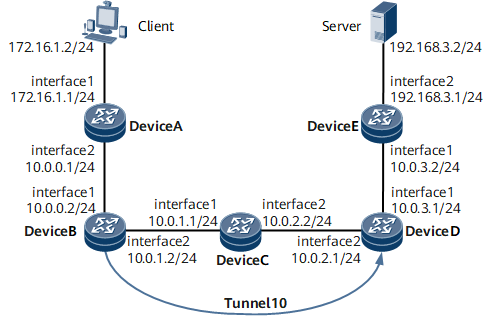
On the network shown in Figure 1, Device A, Device B, Device C, Device D, and Device E are running OSPF. Device B and Device D set up an MPLS TE tunnel with the tunnel interface Tunnel 10, and IGP Shortcut is enabled on Tunnel 10 of Device B. The outbound interface calculated by Device B may be the TE tunnel interface, not the physical interface GE 0/1/8. Tunnel 10 on Device B sends multicast Join packets over a unicast route to the multicast source address. The multicast Join packets are transparent to Device C through which the TE tunnel passes. As a result, Device C cannot generate multicast forwarding entries.
To resolve the problem, enable OSPF local MT on Device B. After local MT is enabled, if the outbound interface of a calculated route is an IGP Shortcut-enabled TE tunnel interface, the route management (RM) module creates an independent Multicast IGP (MIGP) routing table for the multicast protocol, calculates a physical outbound interface for the route, and adds the route to the MIGP routing table. Multicast packets are then forwarded along this route.
Configuration Roadmap
The configuration roadmap is as follows:
Enable OSPF and configure basic OSPF functions on each Device.
Enable PIM-SM on each Device.
Configure an MPLS Resource Reservation Protocol (RSVP)-TE tunnel.
Configure an MPLS TE tunnel and enable IGP Shortcut for it on Device B.
Enable OSPF local MT on Device B.
Data Preparation
To complete the configuration, you need the following data.
- IP address of each interface on each Router, as shown in Table 1.
The TE tunnel interface Tunnel 10 uses the IP address of Loopback 0 and runs the MPLS TE protocol. The destination address of the TE tunnel is 4.4.4.4, and the tunnel ID is 100. The TE tunnel uses RSVP-TE as a signaling protocol.
Procedure
- Assign an IP address to each interface.
Figure 1 shows how to assign an IP address to each interface. For configuration details, see Configuration Files in this section.
- Configure basic OSPF functions.
Configuring Basic OSPF Functions shows how to configure basic OSPF functions. For configuration details, see Configuration Files in this section.
- Configure Protocol Independent Multicast-Sparse Mode (PIM-SM).
# Enable PIM-SM on Device A.
[*DeviceA] multicast routing-enable
[~DeviceA] interface Gigabitethernet 0/1/8
[~DeviceA-GigabitEthernet0/1/8] pim sm
[*DeviceA-GigabitEthernet0/1/8] quit
[*DeviceA] interface Gigabitethernet 0/1/0
[*DeviceA-GigabitEthernet0/1/0] pim sm
[*DeviceA-GigabitEthernet0/1/0] commit
[~DeviceA-GigabitEthernet0/1/0] quit

Enable PIM-SM on each Device. The configurations for Device B, Device C, Device D, and Device E are similar to those on Device A. For configuration details, see Configuration Files in this section.
# Enable Internet Group Management Protocol (IGMP) on GE 0/1/0 of Device A.
[~DeviceA] interface Gigabitethernet 0/1/0
[~DeviceA-GigabitEthernet0/1/0] igmp enable
[*DeviceA-GigabitEthernet0/1/0] igmp version 3
[*DeviceA-GigabitEthernet0/1/0] commit
[~DeviceA-GigabitEthernet0/1/0] quit
# Configure a C-BSR and a C-RP. Configure a C-BSR and a C-RP on Device D.
[*DeviceD] pim
[*DeviceD-pim] c-bsr Gigabitethernet 0/1/0
[*DeviceD-pim] c-rp Gigabitethernet 0/1/0
[*DeviceD-pim] commit
[~DeviceD-pim] quit
# Check the multicast routing table on Device C.
[~DeviceC] display multicast routing-table
Multicast routing table of VPN-Instance: public net
 Total 3 entries

 00001. (192.168.3.8, 224.31.31.31)
       Uptime: 15:03:04
       Upstream Interface: GigabitEthernet0/1/8
       List of 1 downstream interface
           1:  GigabitEthernet0/1/0

 00002. (192.168.3.9, 224.31.31.31)
       Uptime: 15:03:04
       Upstream Interface: GigabitEthernet0/1/8
       List of 1 downstream interface
           1:  GigabitEthernet0/1/0

 00003. (192.168.3.10, 224.31.31.31)
       Uptime: 15:03:04
       Upstream Interface: GigabitEthernet0/1/8
       List of 1 downstream interface
           1:  GigabitEthernet0/1/0
The preceding command output shows information about the multicast routing table on Device C.
- Configure an MPLS RSVP-TE tunnel.
# Configure Device B.
[*DeviceB] mpls lsr-id 2.2.2.2
[*DeviceB] mpls
[*DeviceB-mpls] mpls te
[*DeviceB-mpls] mpls rsvp-te
[*DeviceB-mpls] mpls te cspf
[*DeviceB-mpls] commit
[*DeviceB-mpls] quit
[*DeviceB] interface Gigabitethernet 0/1/8
[*DeviceB-GigabitEthernet0/1/8] mpls
[*DeviceB-GigabitEthernet0/1/8] mpls te
[*DeviceB-GigabitEthernet0/1/8] mpls rsvp-te
[*DeviceB-GigabitEthernet0/1/8] commit
[*DeviceB-GigabitEthernet0/1/8] quit
[*DeviceB] ospf 1
[*DeviceB-ospf-1] enable traffic-adjustment
[*DeviceB-ospf-1] opaque-capability enable
[*DeviceB-ospf-1] area 0.0.0.0
[*DeviceB-ospf-1-area-0.0.0.0] mpls-te enable
[*DeviceB-ospf-1-area-0.0.0.0] commit
[*DeviceB-ospf-1-area-0.0.0.0] quit
# Configure Device C.
[*DeviceC] mpls lsr-id 3.3.3.3
[*DeviceC] mpls
[*DeviceC-mpls] mpls te
[*DeviceC-mpls] mpls rsvp-te
[*DeviceC-mpls] commit
[*DeviceC-mpls] quit
[*DeviceC] interface Gigabitethernet 0/1/0
[*DeviceC-GigabitEthernet0/1/0] mpls
[*DeviceC-GigabitEthernet0/1/0] mpls te
[*DeviceC-GigabitEthernet0/1/0] mpls rsvp-te
[*DeviceC-GigabitEthernet0/1/0] commit
[*DeviceC-GigabitEthernet0/1/0] quit
[*DeviceC] interface Gigabitethernet 0/1/8
[*DeviceC-GigabitEthernet0/1/8] mpls
[*DeviceC-GigabitEthernet0/1/8] mpls te
[*DeviceC-GigabitEthernet0/1/8] mpls rsvp-te
[*DeviceC-GigabitEthernet0/1/8] commit
[*DeviceC-GigabitEthernet0/1/8] quit
[*DeviceC] ospf 1
[*DeviceC-ospf-1] opaque-capability enable
[*DeviceC-ospf-1] area 0.0.0.0
[*DeviceC-ospf-1-area-0.0.0.0] mpls-te enable
[*DeviceC-ospf-1-area-0.0.0.0] commit
[*DeviceC-ospf-1-area-0.0.0.0] quit
# Configure Device D.
[*DeviceD] mpls lsr-id 4.4.4.4
[*DeviceD] mpls
[*DeviceD-mpls] mpls te
[*DeviceD-mpls] mpls rsvp-te
[*DeviceD-mpls] commit
[*DeviceD-mpls] quit
[~DeviceD] interface Gigabitethernet 0/1/8
[*DeviceD-GigabitEthernet0/1/8] mpls
[*DeviceD-GigabitEthernet0/1/8] mpls te
[*DeviceD-GigabitEthernet0/1/8] mpls rsvp-te
[*DeviceD-GigabitEthernet0/1/8] commit
[~DeviceD-GigabitEthernet0/1/8] quit
[*DeviceD] ospf 1
[*DeviceD-ospf-1] opaque-capability enable
[*DeviceD-ospf-1] area 0.0.0.0
[*DeviceD-ospf-1-area-0.0.0.0] mpls-te enable
[*DeviceD-ospf-1-area-0.0.0.0] commit
[*DeviceD-ospf-1-area-0.0.0.0] quit
- Configure an MPLS TE tunnel and enable IGP Shortcut.
# Configure an MPLS TE tunnel and enable IGP Shortcut for it on Device B.
[*DeviceB] interface Tunnel 10
[*DeviceB-Tunnel10] ip address unnumbered interface loopback 0
[*DeviceB-Tunnel10] tunnel-protocol mpls te
[*DeviceB-Tunnel10] destination 4.4.4.4
[*DeviceB-Tunnel10] mpls te tunnel-id 100
[*DeviceB-Tunnel10] mpls te igp shortcut ospf
[*DeviceB-Tunnel10] mpls te igp metric relative -10
[*DeviceB-Tunnel10] commit
[*DeviceB-Tunnel10] quit
# Check the OSPF routing table on Device B. Information shows that an MPLS TE tunnel has been set up.
[*DeviceB] display ip routing-table
Route Flags: R - relay, D - download to fib, T - to vpn-instance, B - black hole route
----------------------------------------------------------------------------
Routing Table: _public_
         Destinations : 14       Routes : 14

  Destination/Mask    Proto    Pre    Cost     Flags    NextHop      Interface
        2.2.2.2/32    Direct   0      0        D        127.0.0.1    InLoopBack0
        3.3.3.3/32    OSPF     10     1        D        10.0.1.1     GigabitEthernet0/1/8
      4.4.4.4/32    OSPF     10     1        D        2.2.2.2      Tunnel10
      5.5.5.5/32    OSPF     10     2        D        2.2.2.2      Tunnel10
        10.0.0.0/24   Direct   0      0        D        10.0.0.2     GigabitEthernet0/1/0
        10.0.0.2/32   Direct   0      0        D        127.0.0.1    InLoopBack0
        10.0.1.0/24   Direct   0      0        D        10.0.1.2     GigabitEthernet0/1/8
        10.0.1.2/32   Direct   0      0        D        127.0.0.1    InLoopBack0
        10.0.2.0/24   OSPF     10     2        D        10.0.1.1     GigabitEthernet0/1/8
                      OSPF     10     2        D        10.0.1.1     Tunnel10
        10.0.3.0/24 OSPF   10   2     D     2.2.2.2   Tunnel10
        127.0.0.0/8   Direct   0      0        D        127.0.0.1    InLoopBack0
        127.0.0.1/32  Direct   0      0        D        127.0.0.1    InLoopBack0
        172.16.1.0/24 OSPF     10     2        D        10.0.0.1     GigabitEthernet0/1/8
        192.168.3.0/24 OSPF 10  3     D     2.2.2.2   Tunnel10
# Check the multicast routing table on Device C.
[*DeviceC] display multicast routing-table
No multicast routing entry is displayed in the multicast routing table on Device C, indicating that Device C has discarded multicast packets.
- Enable OSPF local MT.
# Enable OSPF local MT on Device B.
[*DeviceB] ospf
[*DeviceB-ospf-1] local-mt enable
[*DeviceB-ospf-1] commit
[*DeviceB-ospf-1] quit
- Verify the configuration.
# Check the multicast routing table on Device C.
[*DeviceC] display multicast routing-table
Multicast routing table of VPN-Instance: public net
 Total 3 entries

 00001. (192.168.3.8, 224.31.31.31)
       Uptime: 00:00:19
       Upstream Interface: GigabitEthernet0/1/8
       List of 1 downstream interface
           1:  GigabitEthernet0/1/0

 00002. (192.168.3.9, 224.31.31.31)
       Uptime: 00:00:19
       Upstream Interface: GigabitEthernet0/1/8
       List of 1 downstream interface
           1:  GigabitEthernet0/1/0

 00003. (192.168.3.10, 224.31.31.31)
       Uptime: 00:00:19
       Upstream Interface: GigabitEthernet0/1/8
       List of 1 downstream interface
           1:  GigabitEthernet0/1/0
The preceding command output shows information about the multicast routing table on Device C.
Configuration Files
Device A configuration file
#
 sysname DeviceA
#
 router id 1.1.1.1
#
 multicast routing-enable
#
interface GigabitEthernet0/1/8
 undo shutdown
 ip address 10.0.0.1 255.255.255.0
 pim sm
#
interface GigabitEthernet0/1/0
 undo shutdown
 ip address 172.16.1.1 255.255.255.0
 pim sm
 igmp enable
 igmp version 3
#
interface LoopBack0
 ip address 1.1.1.1 255.255.255.255
#
ospf 1
 area 0.0.0.0
  network 172.16.1.0 0.0.0.255
  network 10.0.0.0 0.0.0.255
  network 1.1.1.1 0.0.0.0
#
return
Device B configuration file
#
 sysname DeviceB
#
 router id 2.2.2.2
#
 multicast routing-enable
#
 mpls lsr-id 2.2.2.2
 mpls
  mpls te
  mpls rsvp-te
  mpls te cspf
#
ospf 1
 opaque-capability enable
 enable traffic-adjustment
 local-mt enable
 area 0.0.0.0
  network 10.0.0.0 0.0.0.255
  network 10.0.1.0 0.0.0.255
  network 2.2.2.2 0.0.0.0
  mpls-te enable
#
interface GigabitEthernet0/1/0
 undo shutdown
 ip address 10.0.0.2 255.255.255.0
 pim sm
#
interface GigabitEthernet0/1/8
 undo shutdown
 ip address 10.0.1.2 255.255.255.0
 pim sm
 mpls
 mpls te
 mpls rsvp-te
#
interface LoopBack0
 ip address 2.2.2.2 255.255.255.255
 pim sm
#
interface Tunnel10
 ip address unnumbered interface LoopBack0
 tunnel-protocol mpls te
 destination 4.4.4.4
 mpls te tunnel-id 100
 mpls te igp shortcut ospf
 mpls te igp metric relative -10
#
pim
 C-BSR LoopBack0
 C-RP LoopBack0
#
return
Device C configuration file
#
 sysname DeviceC
#
 router id 3.3.3.3
#
 multicast routing-enable
#
 mpls lsr-id 3.3.3.3
 mpls
  mpls te
  mpls rsvp-te
#
ospf 1
 opaque-capability enable
 area 0.0.0.0
  network 10.0.1.0 0.0.0.255
  network 10.0.2.0 0.0.0.255
  network 3.3.3.3 0.0.0.0
  mpls-te enable
#
interface GigabitEthernet0/1/0
 undo shutdown
 ip address 10.0.1.1 255.255.255.0
 pim sm
 mpls
 mpls te
 mpls rsvp-te
#
interface GigabitEthernet0/1/8
 undo shutdown
 ip address 10.0.2.2 255.255.255.0
 pim sm
 mpls
 mpls te
 mpls rsvp-te
#
interface LoopBack0
 undo shutdown
 ip address 3.3.3.3 255.255.255.255
 #
return
Device D configuration file
#
 sysname DeviceD
#
 router id 4.4.4.4
#
 multicast routing-enable
#
 mpls lsr-id 4.4.4.4
 mpls
  mpls te
  mpls rsvp-te
#
interface GigabitEthernet0/1/0
 undo shutdown
 ip address 10.0.3.1 255.255.255.0
 pim sm
#
interface GigabitEthernet0/1/8
 undo shutdown
 ip address 10.0.2.1 255.255.255.0
 pim sm
 mpls
 mpls te
 mpls rsvp-te
#
interface LoopBack0
 ip address 4.4.4.4 255.255.255.255
 pim sm
#
ospf 1
 opaque-capability enable
 area 0.0.0.0
  network 10.0.2.0 0.0.0.255
  network 10.0.3.0 0.0.0.255
  network 4.4.4.4 0.0.0.0
  mpls-te enable
#
pim
 C-BSR GigabitEthernet0/1/0
 C-RP GigabitEthernet0/1/0
#
return
Device E configuration file
#
 sysname DeviceE
#
 router id 5.5.5.5
#
 multicast routing-enable
#
interface GigabitEthernet0/1/0
 undo shutdown
 ip address 10.0.3.2 255.255.255.0
 pim sm
#
interface GigabitEthernet0/1/8
 undo shutdown
 ip address 192.168.3.1 255.255.255.0
 pim sm
#
interface LoopBack0
 ip address 5.5.5.5 255.255.255.255
 pim sm
#
ospf 1
 area 0.0.0.0
  network 10.0.3.0 0.0.0.255
  network 192.168.3.0 0.0.0.255
  network 5.5.5.5 0.0.0.0
#
return