Example for Configuring BFD for OSPFv3
This section describes how to configure BFD for OSPFv3. After BFD for OSPFv3 is configured, BFD can rapidly detect link faults and report them to OSPFv3 so that service traffic can be transmitted through the backup link.
Networking Requirements
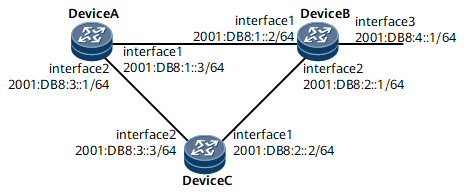
On the network shown in Figure 1, the requirements are as follows:
OSPFv3 runs on Device A, Device B, and Device C.
BFD is enabled in an OSPFv3 process on Device A, Device B, and Device C.
Service traffic is transmitted over the primary link (Device A -> Device B). The link (Device A -> Device C -> Device B) functions as the backup link.
If the primary link fails, BFD can quickly detect the fault and notify OSPFv3 of the fault so that service traffic can be transmitted through the backup link.

Configuration Roadmap
The configuration roadmap is as follows:
Configure basic OSPFv3 functions on each router.
Configure BFD for OSPFv3.
Data Preparation
To complete the configuration, you need the following data:
Router ID of Device A: 1.1.1.1
Router ID of Device B: 2.2.2.2
Router ID of Device C: 3.3.3.3
Minimum interval at which BFD packets are received and sent and local detection multiplier on Device A and Device B
Procedure
- Assign an IPv6 address to each interface. For configuration details, see Configuration Files in this section.
- Configure basic OSPFv3 functions.
# Configure Device A.
[*DeviceA] ospfv3
[*DeviceA-ospfv3-1] router-id 1.1.1.1
[*DeviceA-ospfv3-1] quit
[*DeviceA] interface gigabitethernet 0/1/0
[*DeviceA-GigabitEthernet0/1/0] ospfv3 1 area 0
[*DeviceA-GigabitEthernet0/1/0] quit
[*DeviceA] interface gigabitethernet 0/1/1
[*DeviceA-GigabitEthernet0/1/1] ospfv3 1 area 0.0.0.0
[*DeviceA-GigabitEthernet0/1/1] quit
[*DeviceA] commit
# Configure Device B.
[*DeviceB] ospfv3 1
[*DeviceB-ospfv3-1] router-id 2.2.2.2
[*DeviceB-ospfv3-1] quit
[*DeviceB] interface gigabitethernet 0/1/0
[*DeviceB-GigabitEthernet0/1/0] ospfv3 1 area 0.0.0.0
[*DeviceB-GigabitEthernet0/1/0] quit
[*DeviceB] interface gigabitethernet 0/1/1
[*DeviceB-GigabitEthernet0/1/1] ospfv3 1 area 0.0.0.0
[*DeviceB-GigabitEthernet0/1/1] quit
[*DeviceB] interface gigabitethernet 0/1/2
[*DeviceB-GigabitEthernet0/1/2] ospfv3 1 area 0.0.0.0
[*DeviceB-GigabitEthernet0/1/2] commit
# Configure Device C.
[~DeviceC] ospfv3 1
[*DeviceC-ospfv3-1] router-id 3.3.3.3
[*DeviceC-ospfv3-1] quit
[*DeviceC] interface gigabitethernet 0/1/0
[*DeviceC-GigabitEthernet0/1/0] ospfv3 1 area 0.0.0.0
[DeviceC-GigabitEthernet0/1/0] quit
[*DeviceC] interface gigabitethernet 0/1/1
[*DeviceC-GigabitEthernet0/1/1] ospfv3 1 area 0.0.0.0
[*DeviceC-GigabitEthernet0/1/1] commit
# After the preceding configurations are complete, run the display ospfv3 peer command. The command output shows that neighbor relationships are set up between Device A and Device B, and between Device B and Device C. Use the command output on Device A as an example.
[~DeviceA] display ospfv3 peer verbose
 OSPFv3 Process (100)

 OSPFv3 Area (0.0.0.0)

 Neighbor 1.1.1.1, interface address FE80::3D43:0:8C14:1
    In the area 0.0.0.1 via interface GE0/1/0
    DR is 0.0.0.0 BDR is 0.0.0.0
    Options is 0x000013 (-|R|-|-|E|V6)
    Dead timer due in 00:00:29
    Neighbour is up for 01:08:17
    Database Summary List 0
    Link State Request List 0
    Link State Retransmission List 0
    Neighbour Event: 7
    Neighbour If Id : 0x04
# View information in the OSPFv3 routing table on Device A. The routing table should contain the routes to Device B and Device C.
[~DeviceA] display ospfv3 routing
OSPFv3 Process (1)


Destination                                                 Metric
  Next-hop
2001:DB8:1::/64                                                    1
 directly connected, GE0/1/0
2001:DB8:2::/64                                                    2
 via FE80::E0:9C69:8142:2, GE0/1/1
 via FE80::E0:CE19:8142:1, GE0/1/0
2001:DB8:3::/64                                                    1
 directly connected, GE0/1/1
2001:DB8:4::1/64                                                   1
 via FE80::E0:CE19:8142:1, GE0/1/0
The information shows that the next hop of the route to 2001:DB8:4::1/64 is GigabitEthernet 0/1/0. Traffic is transmitted over the primary link.
- Configure BFD for OSPFv3.
# Enable BFD on Device A globally.
[*DeviceA] bfd
[*DeviceA-bfd] quit
[*DeviceA] ospfv3 1
[*DeviceA-ospfv3-1] bfd all-interfaces enable
[*DeviceA-ospfv3-1] bfd all-interfaces min-transmit-interval 100 min-receive-interval 100 detect-multiplier 4
[*DeviceA-ospfv3-1] commit
# Enable BFD on Device B globally.
[*DeviceB] bfd
[*DeviceB-bfd] quit
[*DeviceB] ospfv3 1
[*DeviceB-ospfv3-1] bfd all-interfaces enable
[*DeviceB-ospfv3-1] bfd all-interfaces min-transmit-interval 100 min-receive-interval 100 detect-multiplier 4
[*DeviceB-ospfv3-1] commit
# Enable BFD on Device C globally.
[*DeviceC] bfd
[*DeviceC-bfd] quit
[*DeviceC] ospfv3 1
[*DeviceC-ospfv3-1] bfd all-interfaces enable
[*DeviceC-ospfv3-1] bfd all-interfaces min-transmit-interval 100 min-receive-interval 100 detect-multiplier 4
[*DeviceC-ospfv3-1] commit
# After the preceding configurations are complete, run the display ospfv3 bfd session command on Device A or Device B. You can view that the status of the BFD session is Up.
Use the command output on Device B as an example.
<DeviceB> display ospfv3 bfd session verbose
* - STALE

OSPFv3 Process (1)
   Neighbor-Id: 1.1.1.1
   BFD Status: Up
   Interface: GE0/1/0
   IPv6-Local-Address: FE80::E0:CE19:8142:1
   IPv6-Remote-Address: FE80::E0:4C3A:143:1

   Total UP/DOWN BFD Session Number : 1 / 0
- Verify the configuration.
# Run the shutdown command on GE 0/1/0 of Device B to simulate a primary link failure.
[~DeviceB] interface gigabitethernet0/1/0
[~DeviceB-GigabitEthernet0/1/0] shutdown
[*DeviceB-GigabitEthernet0/1/0] commit
# Check the routing table on routerDevice A. The command output shows that the next hop on the route to 2001:DB8:4::1/64 is changed to GigabitEthernet 0/1/1. Therefore, traffic is switched to the backup link.
<DeviceA> display ospfv3 routing
OSPFv3 Process (1)


Destination                                                 Metric
  Next-hop
 2001:DB8:1::/64                                                    1
       directly connected, GE0/1/0
 2001:DB8:2::/64                                                    2
       via FE80::E0:9C69:8142:2, GE0/1/1
 2001:DB8:3::/64                                                    1
       directly connected, GE0/1/1
 2001:DB8:4::1/64                                                   2
       via FE80::E0:9C69:8142:2, GE0/1/1
Configuration Files
Device A configuration file
#
sysname DeviceA
#
 bfd
#
ospfv3 1
 router-id 1.1.1.1
 bfd all-interfaces enable
 bfd all-interfaces min-transmit-interval 100 min-receive-interval 100 detect-multiplier 4
 area 0.0.0.0
#
interface gigabitethernet0/1/0
 undo shutdown
 ipv6 enable
 ipv6 address 2001:db8:1::3/64
 ospfv3 1 area 0.0.0.0
#
interface gigabitethernet0/1/1
 undo shutdown
 ipv6 enable
 ipv6 address 2001:db8:3::1/64
 ospfv3 1 area 0.0.0.0
#
return
Device B configuration file
#
sysname DeviceB
#
 bfd
#
ospfv3 1
 router-id 2.2.2.2
 bfd all-interfaces enable
 bfd all-interfaces min-transmit-interval 100 min-receive-interval 100 detect-multiplier 4
 area 0.0.0.0
#
interface gigabitethernet0/1/0
 undo shutdown
 ipv6 enable
 ipv6 address 2001:db8:1::2/64
 ospfv3 1 area 0.0.0.0
#
interface gigabitethernet0/1/1
 undo shutdown
 ipv6 enable
 ipv6 address 2001:db8:2::1/64
 ospfv3 1 area 0.0.0.0
#
interface gigabitethernet0/1/2
 undo shutdown
 ipv6 enable
 ipv6 address 2001:db8:4::1/64
 ospfv3 1 area 0.0.0.0
#
return
Device C configuration file
#
sysname DeviceC
#
ospfv3 1
 router-id 3.3.3.3
 bfd all-interfaces enable
 bfd all-interfaces min-transmit-interval 100 min-receive-interval 100 detect-multiplier 4
 area 0.0.0.0
#
interface gigabitethernet0/1/0
 undo shutdown
 ipv6 enable
 ipv6 address 2001:db8:2::2/64
 ospfv3 1 area 0.0.0.0
#
interface gigabitethernet0/1/1
 undo shutdown
 ipv6 enable
 ipv6 address 2001:db8:3::3/64
 ospfv3 1 area 0.0.0.0
#
return