Example for Configuring a Local PBB VPLS Connection
If two CEs connect to the same PE on a PBB VPLS network, a local PBB VPLS connection can be configured on the PE for the two CEs to communicate.
Networking Requirements
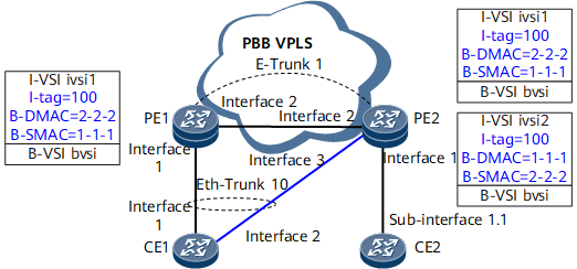
On the PBB VPLS network shown in Figure 1, CE1 and CE2 connect to PE1 and PE2, respectively. To improve access reliability, CE1 is also connected to PE2, and an E-Trunk is configured to determine the master/backup PE status. The E-Trunk protects the PEs and links between CE1 and the PEs.
When no fault occurs, PE1 serves as the master to provide access services for CE1. CE1 communicates with CE2 over the PBB VPLS network. If PE1 or a link between CE1 and PE1 fails, the E-Trunk detects the fault and sends LACP packets to CE1. Upon receipt of the packets, CE1 switches services to PE2 to maintain its communication with CE2. In this situation, CE1 and CE2 communicate over a local PBB VPLS connection.

Interface 1, sub-interface 1.1, interface 2, and interface 3 in this example represent GE 0/1/0, GE 0/1/0.1, GE 0/1/8, and GE 0/1/16, respectively.
Device |
Interface |
IP Address |
|---|---|---|
PE1 |
GE 0/1/0 |
- |
GE 0/1/8 |
10.1.1.1/24 |
|
Loopback0 |
1.1.1.1/32 |
|
PE2 |
GE 0/1/0 |
- |
GE 0/1/8 |
10.1.1.2/24 |
|
GE 0/1/16 |
- |
|
Loopback 0 |
2.2.2.2/32 |
|
CE 1 |
Eth-Trunk 10 |
- |
Eth-Trunk 10.1 |
10.2.1.1/24 |
|
GE 0/1/0 |
- |
|
GE 0/1/8 |
- |
|
CE 2 |
GE 0/1/0.1 |
10.2.1.2/24 |
Configuration Roadmap
The configuration roadmap is as follows:
- Configure an IP address and enable an IGP on each interface to ensure IP connectivity.
- Configure MPLS and MPLS LDP.
- Enable MPLS L2VPN and configure PBB VPLS.
- Configure an E-Trunk to determine the master/backup status of PEs.
Data Preparation
- IP addresses and masks of interfaces on the backbone network
- I-VSI and B-VSI names, VSI IDs, B-SMAC addresses, B-DMAC addresses, and I-tags
- E-Trunk ID, system ID, LACP priority, E-Trunk priority, local and peer IP addresses, and Eth-Trunk ID
Procedure
- Configure interface IP addresses for each CE and PE in accordance with Configuration Files.
- Configure an IGP (OSPF in this example) on each PE.
# Configure PE1.
<PE1> system-view
[~PE1] ospf 1
[*PE1-ospf-1] area 0
[*PE1-ospf-1-area-0.0.0.0] network 1.1.1.1 0.0.0.0
[*PE1-ospf-1-area-0.0.0.0] network 10.1.1.0 0.0.0.255
[*PE1-ospf-1-area-0.0.0.0] quit
[*PE1-ospf-1] quit
[*PE1] commit
# Configure PE2.
<PE2> system-view
[~PE2] ospf 1
[*PE2-ospf-1] area 0
[*PE2-ospf-1-area-0.0.0.0] network 2.2.2.2 0.0.0.0
[*PE2-ospf-1-area-0.0.0.0] network 10.1.1.0 0.0.0.255
[*PE2-ospf-1-area-0.0.0.0] network 10.2.1.0 0.0.0.255
[*PE2-ospf-1-area-0.0.0.0] quit
[*PE2-ospf-1] quit
[*PE2] commit
# After completing the configurations, check OSPF route information. The following example uses the command output on NPE1.
[~PE1] display ospf routing OSPF Process 1 with Router ID 1.1.1.1 Routing Tables Routing for Network Destination Cost Type NextHop AdvRouter Area 1.1.1.1/32 0 Direct 1.1.1.1 1.1.1.1 0.0.0.0 2.2.2.2/32 1 Stub 10.1.1.2 2.2.2.2 0.0.0.0 10.1.1.0/24 1 Direct 10.1.1.1 1.1.1.1 0.0.0.0 Total Nets: 3 Intra Area: 3 Inter Area: 0 ASE: 0 NSSA: 0 - Configure MPLS and MPLS LDP and establish LSPs.
# Configure PE1.
[~PE1] mpls lsr-id 1.1.1.1
[*PE1] mpls
[*PE1-mpls] quit
[*PE1] mpls ldp
[*PE1-mpls-ldp] quit
[*PE1] interface gigabitethernet 0/1/8
[*PE1-GigabitEthernet0/1/8] mpls
[*PE1-GigabitEthernet0/1/8] mpls ldp
[*PE1-GigabitEthernet0/1/8] quit
[*PE1] commit
# Configure PE2.
[~PE2] mpls lsr-id 2.2.2.2
[*PE2] mpls
[*PE2-mpls] quit
[*PE2] mpls ldp
[*PE2-mpls-ldp] quit
[*PE2] interface gigabitethernet 0/1/8
[*PE2-GigabitEthernet0/1/8] mpls
[*PE2-GigabitEthernet0/1/8] mpls ldp
[*PE2-GigabitEthernet0/1/8] quit
[*PE2] commit
# After completing the configurations, check LDP LSP information. The following example uses the command output on PE1.
[~PE1] display mpls ldp session LDP Session(s) in Public Network Codes: LAM(Label Advertisement Mode), SsnAge Unit(DDDD:HH:MM) An asterisk (*) before a session means the session is being deleted. -------------------------------------------------------------------------- PeerID Status LAM SsnRole SsnAge KASent/Rcv -------------------------------------------------------------------------- 2.2.2.2:0 Operational DU Passive 0000:00:00 4/4 -------------------------------------------------------------------------- TOTAL: 1 Session(s) Found. - Configure PBB VPLS.
- Configure I-VSIs.
To expedite service switching, configure the mac-withdraw enable, interface-status-change mac-withdraw enable, and ignore-ac-state commands for the I-VSIs on PE1 and PE2.
# Configure PE1.
[~PE1] vsi ivsi1 i-vsi p2p
[*PE1-vsi-ivsi1] pwsignal ldp
[*PE1-vsi-ivsi1-ldp] vsi-id 10
[*PE1-vsi-ivsi1-ldp] mac-withdraw enable
[*PE1-vsi-ivsi1-ldp] interface-status-change mac-withdraw enable
[*PE1-vsi-ivsi1-ldp] quit
[*PE1-vsi-ivsi1] ignore-ac-state
[*PE1-vsi-ivsi1] pbb i-tag 100
[*PE1-vsi-ivsi1] pbb backbone-source-mac 00e0-fc00-1234
[*PE1-vsi-ivsi1] pbb backbone-destination-mac 00e0-fc12-3456 static
[*PE1-vsi-ivsi1] quit
[*PE1] commit
# Configure PE2.
[~PE2] vsi ivsi1 i-vsi p2p
[*PE2-vsi-ivsi1] pwsignal ldp
[*PE2-vsi-ivsi1-ldp] vsi-id 10
[*PE2-vsi-ivsi1-ldp] mac-withdraw enable
[*PE2-vsi-ivsi1-ldp] interface-status-change mac-withdraw enable
[*PE2-vsi-ivsi1-ldp] quit
[*PE2-vsi-ivsi1] ignore-ac-state
[*PE2-vsi-ivsi1] pbb i-tag 100
[*PE2-vsi-ivsi1] pbb backbone-source-mac 00e0-fc00-1234
[*PE2-vsi-ivsi1] pbb backbone-destination-mac 00e0-fc12-3456 static
[*PE2-vsi-ivsi1] quit
[*PE2] vsi ivsi2 i-vsi p2p
[*PE2-vsi-ivsi2] pwsignal ldp
[*PE2-vsi-ivsi2-ldp] vsi-id 30
[*PE2-vsi-ivsi2-ldp] mac-withdraw enable
[*PE2-vsi-ivsi2-ldp] interface-status-change mac-withdraw enable
[*PE2-vsi-ivsi2-ldp] quit
[*PE2-vsi-ivsi2] pbb i-tag 100
[*PE2-vsi-ivsi2] pbb backbone-source-mac 00e0-fc12-3456
[*PE2-vsi-ivsi2] pbb backbone-destination-mac 00e0-fc00-1234 static
[*PE2-vsi-ivsi2] quit
[*PE2] commit
- Configure I-VSIs.
- # Configure an E-Trunk.
# Configure PE1.
[~PE1] e-trunk 1
[*PE1-e-trunk-1] peer-address 2.2.2.2 source-address 1.1.1.1
[*PE1-e-trunk-1] priority 50
[*PE1-e-trunk-1] quit
[*PE1] interface eth-trunk 10
[*PE1-Eth-Trunk10] e-trunk 1
[*PE1-Eth-Trunk10] quit
[*PE1] commit
# Configure PE2.
[~PE2] e-trunk 1
[*PE2-e-trunk-1] peer-address 1.1.1.1 source-address 2.2.2.2
[*PE2-e-trunk-1] quit
[*PE2] interface eth-trunk 10
[*PE2-Eth-Trunk10] e-trunk 1
[*PE2-Eth-Trunk10] quit
[*PE2] commit
- Bind a BFD session to the E-Trunk.
- Configure CE1 and CE2 to access PEs.
# Configure CE1.
[~CE1] interface eth-trunk 10
[*CE1-Eth-Trunk10] mode lacp-static
[*CE1-Eth-Trunk10] trunkport gigabitethernet 0/1/0 to 0/1/8
[*CE1-Eth-Trunk10] quit
[*CE1] interface eth-trunk10.1
[*CE1-Eth-Trunk10.1] vlan-type dot1q 10
[*CE1-Eth-Trunk10.1] ip address 10.2.1.1 24
[*CE1-Eth-Trunk10.1] quit
[*CE1] commit
# Configure CE2.
[~CE2] interface gigabitethernet 0/1/0.1
[*CE2-GigabitEthernet0/1/0.1] vlan-type dot1q 10
[*CE2-GigabitEthernet0/1/0.1] ip address 10.2.1.2 24
[*CE2-GigabitEthernet0/1/0.1] quit
[*CE2] commit
- Verify the configuration.
After the configurations are complete, CE1 and CE2 can ping each other. The following uses the command output on CE1.
[~CE1] ping 10.2.1.2
PING 10.2.1.2: 56  data bytes, press CTRL_C to break
    Reply from 10.2.1.2: bytes=56 Sequence=1 ttl=255 time=3 ms
    Reply from 10.2.1.2: bytes=56 Sequence=2 ttl=255 time=1 ms
    Reply from 10.2.1.2: bytes=56 Sequence=3 ttl=255 time=2 ms
    Reply from 10.2.1.2: bytes=56 Sequence=4 ttl=255 time=1 ms
    Reply from 10.2.1.2: bytes=56 Sequence=5 ttl=255 time=2 ms

  --- 10.2.1.2 ping statistics ---
    5 packet(s) transmitted
    5 packet(s) received
    0.00% packet loss
    round-trip min/avg/max = 1/1/3 ms
# After completing the configurations, run the display e-trunk command on PE1 and PE2. The command output shows that the E-Trunk between PE1 and PE2 is working properly, PE1 is in the Master state, PE2 is in the Backup state, and Eth-Trunk 10 in the E-Trunk is Up on PE1 and Down on PE2. The following example uses the command output on PE1.
[~PE1] display e-trunk 1
                            The E-Trunk information
E-TRUNK-ID : 1                          Revert-Delay-Time (s) : 120
Priority : 50                           System-ID : 00e0-fc56-7812
Peer-IP : 2.2.2.2                       Source-IP : 1.1.1.1
State :                             The E-Trunk information
E-TRUNK-ID : 1                          Revert-Delay-Time (s) : 120
Priority : 50                           System-ID : 00e0-fc56-7812
Peer-IP : 2.2.2.2                       Source-IP : 1.1.1.1
State : Master                         Causation : PRI
Send-Period (100ms) : 10                Fail-Time (100ms) : 200
Receive : 6445                          Send : 6536
RecDrop : 0                             SndDrop : 0
Peer-Priority : 100                     Peer-System-ID : 00e0-fc34-5678
Peer-Fail-Time (100ms) : 200            BFD-Session : hello
Description : -
Dynamic-BFD : Disabled                  BFD-State : -
TX (ms) : -                             RX (ms) : -
Multiplier : -
--------------------------------------------------------------------------------
                            The Member information
Type      ID  LocalPhyState  Work-Mode     State   Causation        Remote-ID
Eth-Trunk 10  Down           auto          Master  ETRUNK_MASTER    10                          Causation : PRI
Send-Period (100ms) : 10                Fail-Time (100ms) : 200
Receive : 6445                          Send : 6536
RecDrop : 0                             SndDrop : 0
Peer-Priority : 100                     Peer-System-ID : 00e0-fc34-5678
Peer-Fail-Time (100ms) : 200            BFD-Session : hello
Description : -
Dynamic-BFD : Disabled                  BFD-State : -
TX (ms) : -                             RX (ms) : -
Multiplier : -
--------------------------------------------------------------------------------
                            The Member information
Type      ID  LocalPhyState  Work-Mode     State   Causation        Remote-ID
Eth-Trunk 10  Up             auto          Master  ETRUNK_MASTER    10
# Run the shutdown command on the interface connecting CE1 to PE1. The interface goes Down. Then, run the display e-trunk command on PE2. The command output shows that Eth-Trunk 10 goes Up on PE2, meaning that CE1 switches traffic from PE1 to PE2, implementing non-stop service transmission.
[~CE1] interface gigabitethernet 0/1/0
[*CE1-GigabitEthernet0/1/0] shutdown
[*CE1-GigabitEthernet0/1/0] quit
[~PE1] display e-trunk 1
                            The E-Trunk information
E-TRUNK-ID : 1                          Revert-Delay-Time (s) : 120
Priority : 50                           System-ID : 00e0-fc56-7812
Peer-IP : 2.2.2.2                       Source-IP : 1.1.1.1
State :                             The E-Trunk information
E-TRUNK-ID : 1                          Revert-Delay-Time (s) : 120
Priority : 50                           System-ID : 00e0-fc56-7812
Peer-IP : 2.2.2.2                       Source-IP : 1.1.1.1
State : Master                         Causation : PRI
Send-Period (100ms) : 10                Fail-Time (100ms) : 200
Receive : 6445                          Send : 6536
RecDrop : 0                             SndDrop : 0
Peer-Priority : 100                     Peer-System-ID : 00e0-fc34-5678
Peer-Fail-Time (100ms) : 200            BFD-Session : hello
Description : -
Dynamic-BFD : Disabled                  BFD-State : -
TX (ms) : -                             RX (ms) : -
Multiplier : -
--------------------------------------------------------------------------------
                            The Member information
Type      ID  LocalPhyState  Work-Mode     State   Causation        Remote-ID
Eth-Trunk 10  Down           auto          Master  ETRUNK_MASTER    10                          Causation : PRI
Send-Period (100ms) : 10                Fail-Time (100ms) : 200
Receive : 6445                          Send : 6536
RecDrop : 0                             SndDrop : 0
Peer-Priority : 100                     Peer-System-ID : 00e0-fc34-5678
Peer-Fail-Time (100ms) : 200            BFD-Session : hello
Description : -
Dynamic-BFD : Disabled                  BFD-State : -
TX (ms) : -                             RX (ms) : -
Multiplier : -
--------------------------------------------------------------------------------
                            The Member information
Type      ID  LocalPhyState  Work-Mode     State   Causation        Remote-ID
Eth-Trunk 10  Down           auto          Backup  ETRUNK_MASTER    10
[~CE1] ping 10.1.1.2
PING 10.2.1.2: 56  data bytes, press CTRL_C to break
    Reply from 10.2.1.2: bytes=56 Sequence=1 ttl=255 time=3 ms
    Reply from 10.2.1.2: bytes=56 Sequence=2 ttl=255 time=1 ms
    Reply from 10.2.1.2: bytes=56 Sequence=3 ttl=255 time=2 ms
    Reply from 10.2.1.2: bytes=56 Sequence=4 ttl=255 time=1 ms
    Reply from 10.2.1.2: bytes=56 Sequence=5 ttl=255 time=2 ms

  --- 10.2.1.2 ping statistics ---
    5 packet(s) transmitted
    5 packet(s) received
    0.00% packet loss
    round-trip min/avg/max = 1/1/3 ms
Configuration Files
CE1 configuration file
#
sysname CE1
#
interface Eth-Trunk10
 mode lacp-static
#
interface Eth-Trunk10.1
 vlan-type dot1q 10
 ip address 10.1.1.1 255.255.255.0
#
interface GigabitEthernet0/1/0
 undo shutdown
 eth-trunk 10
#
interface GigabitEthernet0/1/8
 undo shutdown
 eth-trunk 10
#
return
PE1 configuration file
#
sysname PE1
#
bfd
#
mpls lsr-id 1.1.1.1
#
mpls
#
mpls l2vpn
#
vsi bvsi1 b-vsi
 pwsignal ldp
  vsi-id 20
  peer 2.2.2.2
#
vsi ivsi1 i-vsi p2p
 pwsignal ldp
  vsi-id 10
  mac-withdraw enable
  interface-status-change mac-withdraw enable
 ignore-ac-state
 pbb i-tag 100
 pbb backbone-source-mac 00e0-fc00-1234
 pbb backbone-destination-mac 00e0-fc12-3456 static
 pbb binding b-vsi bvsi1
#
mpls ldp
#
e-trunk 1
 priority 50
 peer-address 2.2.2.2 source-address 1.1.1.1
 e-trunk track bfd-session session-name hello
#
interface Eth-Trunk10
 mode lacp-static
 e-trunk 1
#
interface Eth-Trunk10.1
 vlan-type dot1q 10
 l2 binding vsi ivsi1
#
interface GigabitEthernet0/1/0
 undo shutdown
 eth-trunk 10
#
interface GigabitEthernet0/1/8
 undo shutdown
 ip address 10.1.1.1 255.255.255.0
 mpls
 mpls ldp
#
interface LoopBack0
 ip address 1.1.1.1 255.255.255.0
#
bfd hello bind peer-ip 2.2.2.2 source-ip 1.1.1.1
 discriminator local 1
 discriminator remote 2
#
ospf 1
 area 0.0.0.0
  network 1.1.1.1 0.0.0.0
  network 10.1.1.0 0.0.0.255
#
return
PE2 configuration file
#
sysname PE2
#
bfd
#
mpls lsr-id 2.2.2.2
#
mpls
#
mpls l2vpn
#
vsi bvsi1 b-vsi
 pwsignal ldp
  vsi-id 20
  peer 1.1.1.1
#
vsi ivsi1 i-vsi p2p
 pwsignal ldp
  vsi-id 10
  mac-withdraw enable
  interface-status-change mac-withdraw enable
 ignore-ac-state
 pbb i-tag 100
 pbb backbone-source-mac 00e0-fc00-1234
 pbb backbone-destination-mac 00e0-fc12-3456 static
 pbb binding b-vsi bvsi1
#
vsi ivsi2 i-vsi p2p
 pwsignal ldp
  vsi-id 30
  mac-withdraw enable
  interface-status-change mac-withdraw enable
 pbb i-tag 100
 pbb backbone-source-mac 00e0-fc12-3456
 pbb backbone-destination-mac 00e0-fc00-1234 static
 pbb binding b-vsi bvsi1
#
mpls ldp
#
e-trunk 1
 peer-address 1.1.1.1 source-address 2.2.2.2
 e-trunk track bfd-session session-name hello
#
interface Eth-Trunk10
 mode lacp-static
 e-trunk 1
#
interface Eth-Trunk10.1
 vlan-type dot1q 10
 l2 binding vsi ivsi1
#
interface GigabitEthernet0/1/0.1
 vlan-type dot1q 10
 l2 binding vsi ivsi2
#
interface GigabitEthernet0/1/16
 undo shutdown
 eth-trunk 10
#
interface GigabitEthernet0/1/8
 undo shutdown
 ip address 10.1.1.2 255.255.255.0
 mpls
 mpls ldp
#
interface LoopBack0
 ip address 2.2.2.2 255.255.255.0
#
bfd hello bind peer-ip 1.1.1.1 source-ip 2.2.2.2
 discriminator local 2
 discriminator remote 1
#
ospf 1
 area 0.0.0.0
  network 2.2.2.2 0.0.0.0
  network 10.1.1.0 0.0.0.255
#
return
CE2 configuration file
#
sysname CE2
#
interface GigabitEthernet0/1/0
 undo shutdown
#
interface GigabitEthernet0/1/0.1
 vlan-type dot1q 10
 ip address 10.1.1.2 255.255.255.0
#
return