Example for Configuring PBB VPLS with Multiple I-VSIs Bound to the Same B-VSI
To enable multiple CEs to communicate over a PBB VPLS network, you have to bind multiple I-VSIs to the same B-VSI.
Networking Requirements
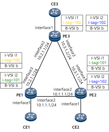
On the shown in Figure 1, PE1, PE2, and PE3 are fully connected, and each CE is single-homed to a PE. To enable CE1, CE2, and CE3 to communicate over a PBB VPLS network, configure a B-VSI and two I-VSIs on each PE and bind the I-VSIs on each PE to the B-VSI on that PE. Different I-VSIs can be used to isolate broadcast domains.

Configuration Roadmap
The configuration roadmap is as follows:
- Configure an IP address and enable an IGP on each interface to ensure IP connectivity.
- Configure MPLS and MPLS LDP.
- Enable MPLS L2VPN and configure PBB VPLS.
Data Preparation
- IP addresses and masks of interfaces on the backbone network
- I-VSI and B-VSI names, VSI IDs, B-SMAC addresses, B-DMAC addresses, and I-tags
Procedure
- Configure interface IP addresses for each CE and PE in accordance with Configuration Files.
- Configure an IGP (OSPF in this example) on each PE.
# Configure PE1.
<PE1> system-view
[~PE1] ospf 1
[*PE1-ospf-1] area 0
[*PE1-ospf-1-area-0.0.0.0] network 1.1.1.1 0.0.0.0
[*PE1-ospf-1-area-0.0.0.0] network 10.1.1.0 0.0.0.255
[*PE1-ospf-1-area-0.0.0.0] network 10.2.1.0 0.0.0.255
[*PE1-ospf-1-area-0.0.0.0] quit
[*PE1-ospf-1] quit
[*PE1] commit
# Configure PE2.
<PE2> system-view
[~PE2] ospf 1
[*PE2-ospf-1] area 0
[*PE2-ospf-1-area-0.0.0.0] network 2.2.2.2 0.0.0.0
[*PE2-ospf-1-area-0.0.0.0] network 10.1.1.0 0.0.0.255
[*PE2-ospf-1-area-0.0.0.0] network 10.3.1.0 0.0.0.255
[*PE2-ospf-1-area-0.0.0.0] quit
[*PE2-ospf-1] quit
[*PE2] commit
# Configure PE3.
<PE3> system-view
[~PE3] ospf 1
[*PE3-ospf-1] area 0
[*PE3-ospf-1-area-0.0.0.0] network 3.3.3.3 0.0.0.0
[*PE3-ospf-1-area-0.0.0.0] network 10.2.1.0 0.0.0.255
[*PE3-ospf-1-area-0.0.0.0] network 10.3.1.0 0.0.0.255
[*PE3-ospf-1-area-0.0.0.0] quit
[*PE3-ospf-1] quit
[*PE3] commit
After completing the configurations, check OSPF route information. The following example uses the command output on PE1.
[~PE1] display ospf routing OSPF Process 1 with Router ID 10.1.1.1 Routing Tables Routing for Network Destination Cost Type NextHop AdvRouter Area 1.1.1.1/32 0 Direct 1.1.1.1 10.1.1.1 0.0.0.0 2.2.2.2/32 1 Stub 10.1.1.2 10.1.1.2 0.0.0.0 3.3.3.3/32 1 Stub 10.2.1.2 10.2.1.2 0.0.0.0 10.1.1.0/24 1 Direct 10.1.1.1 10.1.1.1 0.0.0.0 10.2.1.0/24 1 Direct 10.2.1.1 10.1.1.1 0.0.0.0 10.3.1.0/24 2 Stub 10.2.1.2 10.2.1.2 0.0.0.0 Total Nets: 6 Intra Area: 6 Inter Area: 0 ASE: 0 NSSA: 0 - Configure MPLS and MPLS LDP and establish LSPs.
# Configure PE1.
[~PE1] mpls lsr-id 1.1.1.1
[*PE1] mpls
[*PE1-mpls] quit
[*PE1] mpls ldp
[*PE1-mpls-ldp] quit
[*PE1] interface gigabitethernet 0/1/8
[*PE1-GigabitEthernet0/1/8] mpls
[*PE1-GigabitEthernet0/1/8] mpls ldp
[*PE1-GigabitEthernet0/1/8] quit
[*PE1] interface gigabitethernet 0/1/16
[*PE1-GigabitEthernet0/1/16] mpls
[*PE1-GigabitEthernet0/1/16] mpls ldp
[*PE1-GigabitEthernet0/1/16] quit
[*PE1] commit
# Configure PE2.
[~PE2] mpls lsr-id 2.2.2.2
[*PE2] mpls
[*PE2-mpls] quit
[*PE2] mpls ldp
[*PE2-mpls-ldp] quit
[*PE2] interface gigabitethernet 0/1/8
[*PE2-GigabitEthernet0/1/8] mpls
[*PE2-GigabitEthernet0/1/8] mpls ldp
[*PE2-GigabitEthernet0/1/8] quit
[*PE2] interface gigabitethernet 0/1/16
[*PE2-GigabitEthernet0/1/16] mpls
[*PE2-GigabitEthernet0/1/16] mpls ldp
[*PE2-GigabitEthernet0/1/16] quit
[*PE2] commit
# Configure PE3.
[~PE3] mpls lsr-id 3.3.3.3
[*PE3] mpls
[*PE3-mpls] quit
[*PE3] mpls ldp
[*PE3-mpls-ldp] quit
[*PE3] interface gigabitethernet 0/1/8
[*PE3-GigabitEthernet0/1/8] mpls
[*PE3-GigabitEthernet0/1/8] mpls ldp
[*PE3-GigabitEthernet0/1/8] quit
[*PE3] interface gigabitethernet 0/1/16
[*PE3-GigabitEthernet0/1/16] mpls
[*PE3-GigabitEthernet0/1/16] mpls ldp
[*PE3-GigabitEthernet0/1/16] quit
[*PE3] commit
# After completing the configurations, check LDP LSP information. The following example uses the command output on PE1.
[~PE1] display mpls ldp session LDP Session(s) in Public Network Codes: LAM(Label Advertisement Mode), SsnAge Unit(DDDD:HH:MM) An asterisk (*) before a session means the session is being deleted. -------------------------------------------------------------------------- PeerID Status LAM SsnRole SsnAge KASent/Rcv -------------------------------------------------------------------------- 2.2.2.2:0 Operational DU Passive 0000:00:00 4/4 3.3.3.3:0 Operational DU Passive 0000:00:00 1/1 -------------------------------------------------------------------------- TOTAL: 2 Session(s) Found. - Configure PBB VPLS.
- Configure CEs to access PEs.
# Configure CE1.
[~CE1] interface gigabitethernet 0/1/0.1
[*CE1-GigabitEthernet0/1/0.1] vlan-type dot1q 10
[*CE1-GigabitEthernet0/1/0.1] ip address 10.10.1.1 24
[*CE1-GigabitEthernet0/1/0.1] quit
[*CE1] interface gigabitethernet 0/1/0.2
[*CE1-GigabitEthernet0/1/0.2]vlan-type dot1q 20
[*CE1-GigabitEthernet0/1/0.1] ip address 10.20.1.1 24
[*CE1-GigabitEthernet0/1/0.1] quit
[*CE1] commit
# Configure CE2.
[~CE2] interface gigabitethernet 0/1/0.1
[*CE2-GigabitEthernet0/1/0.1] vlan-type dot1q 20
[*CE2-GigabitEthernet0/1/0.1] ip address 10.20.1.2 24
[*CE2-GigabitEthernet0/1/0.1] quit
[*CE2] interface gigabitethernet 0/1/0.2
[*CE2-GigabitEthernet0/1/0.2]vlan-type dot1q 30
[*CE2-GigabitEthernet0/1/0.2] ip address 10.30.1.1 24
[*CE2-GigabitEthernet0/1/0.2] quit
[*CE2] commit
# Configure CE3.
[~CE2] interface gigabitethernet 0/1/0.1
[*CE2-GigabitEthernet0/1/0.1] vlan-type dot1q 10
[*CE2-GigabitEthernet0/1/0.1] ip address 10.10.1.2 24
[*CE2-GigabitEthernet0/1/0.1] quit
[*CE2] interface gigabitethernet 0/1/0.2
[*CE2-GigabitEthernet0/1/0.2]vlan-type dot1q 30
[*CE2-GigabitEthernet0/1/0.2] ip address 10.30.1.2 24
[*CE2-GigabitEthernet0/1/0.2] quit
[*CE2] commit
- Verify the configuration.
After the configurations are complete, CE1, CE2, and CE3 can ping each other. The following uses the command output on CE1.
[~CE1] ping 10.30.1.2
PING 10.30.1.2: 56  data bytes, press CTRL_C to break
Reply from 10.30.1.2: bytes=56 Sequence=1 ttl=255 time=3 ms
Reply from 10.30.1.2: bytes=56 Sequence=2 ttl=255 time=1 ms
Reply from 10.30.1.2: bytes=56 Sequence=3 ttl=255 time=2 ms
Reply from 10.30.1.2: bytes=56 Sequence=4 ttl=255 time=1 ms
Reply from 10.30.1.2: bytes=56 Sequence=5 ttl=255 time=2 ms

  --- 10.30.1.2 ping statistics ---
5 packet(s) transmitted
5 packet(s) received
0.00% packet loss
round-trip min/avg/max = 1/1/3 ms
Configuration Files
CE1 configuration file
#
sysname CE1
#
interface GigabitEthernet0/1/0
 undo shutdown
#
interface GigabitEthernet0/1/0.1
 vlan-type dot1q 10
 ip address 10.10.1.1 255.255.255.0
#
interface GigabitEthernet0/1/0.2
 vlan-type dot1q 20
 ip address 10.20.1.1 255.255.255.0
#
return
PE1 configuration file
#
sysname PE1
#
mpls lsr-id 1.1.1.1
mpls
#
mpls l2vpn
#
vsi bvsi1 b-vsi
 pwsignal ldp
  vsi-id 100
  peer 2.2.2.2
  peer 3.3.3.3
 pbb backbone-source-mac 00e0-fc00-1234
#
mpls ldp
vsi ivsi1 i-vsi p2p
 pwsignal ldp
  vsi-id 10
 pbb i-tag 100
 pbb backbone-destination-mac 00e0-fc34-5678 static
 pbb binding b-vsi bvsi1
#
vsi ivsi2 i-vsi p2p
 pwsignal ldp
  vsi-id 20
 pbb i-tag 101
 pbb backbone-destination-mac 00e0-fc12-3456 static
 pbb binding b-vsi bvsi1
#
interface GigabitEthernet0/1/0
 undo shutdown
#
interface GigabitEthernet0/1/0.1
 vlan-type dot1q 10
 l2 binding vsi ivsi1
#
interface GigabitEthernet0/1/0.2
 vlan-type dot1q 20
 l2 binding vsi ivsi2
#
interface GigabitEthernet0/1/8
 undo shutdown
 ip address 10.1.1.1 255.255.255.0
 mpls
 mpls ldp
#
interface GigabitEthernet0/1/16
 undo shutdown
 ip address 10.2.1.1 255.255.255.0
 mpls
 mpls ldp
#
interface LoopBack0
 ip address 1.1.1.1 255.255.255.255
#
ospf 1
 area 0.0.0.0
  network 1.1.1.1 0.0.0.0
  network 10.1.1.0 0.0.0.255
  network 10.2.1.0 0.0.0.255
#
return
PE2 configuration file
#
sysname PE2
#
mpls lsr-id 2.2.2.2
mpls
#
mpls l2vpn
#
vsi bvsi1 b-vsi
 pwsignal ldp
  vsi-id 100
  peer 1.1.1.1
  peer 3.3.3.3
 pbb backbone-source-mac 00e0-fc12-3456
#
vsi ivsi1 i-vsi p2p
 pwsignal ldp
  vsi-id 10
 pbb i-tag 101
 pbb backbone-destination-mac 00e0-fc00-1234 static
 pbb binding b-vsi bvsi1
#
vsi ivsi2 i-vsi p2p
 pwsignal ldp
  vsi-id 20
 pbb i-tag 102
 pbb backbone-destination-mac 00e0-fc34-5678 static
 pbb binding b-vsi bvsi1
#
mpls ldp
#
interface GigabitEthernet0/1/0
 undo shutdown
#
interface GigabitEthernet0/1/0.1
 vlan-type dot1q 10
 l2 binding vsi ivsi1
#
interface GigabitEthernet0/1/0.2
 vlan-type dot1q 20
 l2 binding vsi ivsi2
#
interface GigabitEthernet0/1/8
 undo shutdown
 ip address 10.1.1.2 255.255.255.0
 mpls
 mpls ldp
#
interface GigabitEthernet0/1/16
 undo shutdown
 ip address 10.3.1.1 255.255.255.0
 mpls
 mpls ldp
#
interface LoopBack0
 ip address 2.2.2.2 255.255.255.255
#
ospf 1
 area 0.0.0.0
  network 2.2.2.2 0.0.0.0
  network 10.1.1.0 0.0.0.255
  network 10.2.1.0 0.0.0.255
#
return
PE3 configuration file
#
sysname PE3
#
mpls lsr-id 3.3.3.3
mpls
#
mpls l2vpn
#
vsi bvsi1 b-vsi
 pwsignal ldp
  vsi-id 100
  peer 1.1.1.1
  peer 2.2.2.2
 pbb backbone-source-mac 00e0-fc34-5678
#
vsi ivsi1 i-vsi p2p
 pwsignal ldp
  vsi-id 10
 pbb i-tag 100
 pbb backbone-destination-mac 00e0-fc00-1234 static
 pbb binding b-vsi bvsi1
#
vsi ivsi2 i-vsi p2p
 pwsignal ldp
  vsi-id 20
 pbb i-tag 102
 pbb backbone-destination-mac 00e0-fc12-3456 static
 pbb binding b-vsi bvsi1
#
mpls ldp
#
interface GigabitEthernet0/1/0
 undo shutdown
#
interface GigabitEthernet0/1/0.1
 vlan-type dot1q 10
 l2 binding vsi ivsi1
#
interface GigabitEthernet0/1/0.2
 vlan-type dot1q 20
 l2 binding vsi ivsi2
#
interface GigabitEthernet0/1/8
 undo shutdown
 ip address 10.1.1.2 255.255.255.0
 mpls
 mpls ldp
#
interface GigabitEthernet0/1/16
 undo shutdown
 ip address 10.3.1.2 255.255.255.0
 mpls
 mpls ldp
#
interface LoopBack0
 ip address 3.3.3.3 255.255.255.255
#
ospf 1
 area 0.0.0.0
  network 3.3.3.3 0.0.0.0
  network 10.2.1.0 0.0.0.255
  network 10.3.1.0 0.0.0.255
#
return
CE2 configuration file
#
sysname CE2
#
interface GigabitEthernet0/1/0
 undo shutdown
#
interface GigabitEthernet0/1/0.1
 vlan-type dot1q 20
 ip address 10.20.1.1 255.255.255.0
#
interface GigabitEthernet0/1/0.2
 vlan-type dot1q 30
 ip address 10.30.1.1 255.255.255.0
#
return
CE3 configuration file
#
 sysname CE3
#
interface GigabitEthernet0/1/0
 undo shutdown
#
interface GigabitEthernet0/1/0.1
 vlan-type dot1q 10
 ip address 10.10.1.2 255.255.255.0
#
interface GigabitEthernet0/1/0.2
 vlan-type dot1q 30
 ip address 10.30.1.2 255.255.255.0
#
return