BIERv6 Ping/Tracert
On a BIERv6 network, the control plane (responsible for BIERv6 establishment) cannot detect failures to forward data over the multicast tunnel, making network maintenance difficult. BIERv6 ping and tracert can be used to detect such failures and quickly locate faulty nodes. Both BIERv6 ping and tracert check network connectivity and host reachability, and BIERv6 tracert can also locate failure points.
BIERv6 Ping
On the network shown in Figure 1, PEs are edge nodes on the BIERv6 network. PE1 connects to the multicast source, PE2 through PE6 connect to multicast users, and P is a transmission node. PE2 can function as either a transmission node or a leaf node.
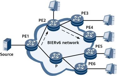
The BIERv6 ping process from PE1 to PE2 and from PE1 to PE4 is as follows:
- PE1 initiates a BIERv6 ping test and encapsulates a BIERv6 ping request packet in the format shown in Figure 2. The source address encapsulated into the IPv6 header is an IPv6 address of the VPN to which the multicast traffic belongs, and the destination address is the End.BIER SID of the next-hop device. The specified target BFR-ID is encapsulated into BIER-Header and BIER OAM. BIER-Header is used to guide packet replication and forwarding, and BIER OAM is used for verification on the control plane.

- Because the BitString length cannot be dynamically negotiated, you need to specify the length manually.
- Currently, only detection based on a single BitString is supported. Therefore, the target BFR-IDs entered by users must be within the same SI range.
- When PE2 functions as a transmission node, it searches the IPv6 FIB table based on the destination address and finds that this address is a local End.BIER SID. PE2 then performs the following actions according to the BIER forwarding process:
- Checks whether the NextHdr field in the IPv6 header is 60. If not, PE2 considers the packet abnormal and discards it.
- If the NextHdr value is 60, PE2 obtains the BIFT-ID value from the packet and searches the Incoming Label Map (ILM) of BIERv6 for the next-hop label forwarding entry (NHLFE). It then calculates the set of outbound interfaces on which traffic needs to be replicated and sent from the obtained NHLFE table based on the BitString information in the packet and performs the corresponding operations. When sending the packet, PE2 changes the destination address of the packet to the End.BIER SID of the next-hop node, and keeps the source address unchanged.
- When PE2 functions as a leaf node, after receiving a packet, PE2 or PE4 matches the BFR-ID of the local device according to the BitString information in the BIER-Header. PE2 or PE4 then determines that the packet needs to be sent to the control plane for processing according to the destination address in the inner IPv6 Header. After receiving the packet, the control plane returns a response packet to PE1 through a route.
- PE1 displays the detection result.
- If no response is received within the timeout period after a request packet is sent, the message "Request time out" is displayed.
- If a response is received within a specified period after a request packet is sent, statistics are collected and displayed based on the BFR-ID of the received packet.
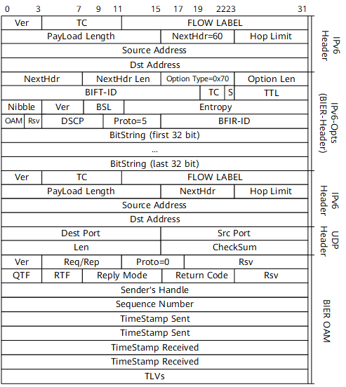
For details about the fields in a BIERv6 ping request packet, see Table 1.
Field |
Description |
|---|---|
Ver |
Version number. |
TC |
Traffic type. |
FLOW LABEL |
Flow label, which is used to differentiate packets at the network layer. |
Payload Length |
Payload length, indicating the length of the packet excluding the IPv6 packet header. |
NextHdr |
Next header. |
Hop Limit |
Hop limit. |
Source Address |
Source IP address of the packet. |
Dst Address |
Destination IP address of the packet. |
NextHdr Len |
Length of the next header. |
Option Type |
Option type. |
Option Len |
Option length. |
BIFT-ID |
BIER forwarding table ID. |
S |
Bottom of a label stack. |
TTL |
Time to live. For ping packets, the default value is 255. For tracert packets, the value starts from 1. |
Nibble |
Half byte. |
BSL |
Length of BitString. |
Entropy |
Entropy value. |
OAM |
Management and maintenance identifier. |
Rsv |
Reserved bit, which must be 0. |
DSCP |
DiffServ Codepoint (DSCP). |
Proto |
Next protocol type. |
BFIR-ID |
BFIR ID. |
BitString |
Bit string. |
Dest Port |
Destination port number of a packet. |
Src Port |
Source port number of a packet. |
Len |
Packet length. |
CheckSum |
Verification field. |
Req/Rep |
Packet type. The value 1 indicates a request packet, and the value 2 indicates a response packet. |
QTF |
Format of the timestamp in a request packet. The value 2 indicates the NTP format, and the value 3 indicates the Precision Time Protocol (PTP) format. If other values are used, an error is reported. |
RTF |
Format of the timestamp in a response packet. The value 2 indicates the NTP format, and the value 3 indicates the Precision Time Protocol (PTP) format. If other values are used, an error is reported. |
Reply Mode |
Reply mode. The value 1 indicates no reply, the value 2 indicates reply through IPv4/IPv6 UDP, and the value 4 indicates reply through BIER. Currently, only UDP is supported. |
Return Code |
The request packet must be set to 0. The response packet has the following settings:
|
Sender's Handle |
Sender handle, which is set in the request packet and returned without any change in the response packet. |
Sequence Number |
Sequence number, which is set in the request packet and returned without any change in the response packet. |
TimeStamp Sent |
Sending timestamp. |
TimeStamp Received |
Receiving timestamp. |
TLVs |
TLV encapsulated into the data area. |
BIERv6 Tracert
As shown in Figure 1, PEs are edge nodes on the BIERv6 network. PE1 connects to the multicast source, PE2 through PE6 connect to multicast users, and P is a transmission node. PE2 can function as either a transmission node or a leaf node. The process of the BIERv6 tracert test from PE1 to PE4 is as follows:
- PE1 initiates a BIERv6 tracert test and encapsulates a BIERv6 tracert request packet in the format shown in Figure 2. The source address encapsulated into the IPv6 header is an IPv6 address of the VPN to which the multicast traffic belongs, and the destination address is the End.BIER SID of the next-hop device. The specified target BFR-ID is encapsulated into BIER-Header and BIER OAM. BIER-Header is used to guide packet replication and forwarding, and BIER OAM is used for verification on the control plane. The Hop Limit field (equivalent to TTL in IPv4) in the outer IPv6 header is set to 64, and the TTL field in BIER-Header is initially set to 1. Each time a BIERv6 tracert packet passes through a BIERv6 device, the value of the TTL field in BIER-Header decreases by 1. Each time a BIERv6 tracert packet passes through a non-BIERv6 device, the value of the Hop Limit field in the IPv6 Header decreases by 1.
- Because the BitString length cannot be dynamically negotiated, you need to specify the length manually.
- Currently, only detection based on a single BitString is supported. Therefore, the target BFR-IDs entered by users must be within the same SI range.
- After receiving the packet, PE2 (transmission node) searches the IPv6 FIB table based on the destination address and finds that this address is a local End.BIER SID. In this case, the subsequent actions are performed according to the BIER forwarding process. If the TTL field in BIER-Header is 0, PE2 needs to send the packet to the control plane for processing. After receiving the packet, the control plane returns a response packet to PE1 through a route.
- After receiving the response packet from PE2, PE1 increases the value of the TTL field in BIER-Header by 1 (the value is now set to 2) and continues to send the BIERv6 tracert packet.
- After receiving the packet, PE4 (leaf node) searches the IPv6 FIB table based on the destination address and finds that this address is a local End.BIER SID. In this case, the subsequent actions are performed according to the BIER forwarding process. If the TTL field in BIER-Header is 0, PE4 needs to send the packet to the control plane for processing. After receiving the packet, the control plane returns a response packet to PE1 through a route.
- After receiving the response packet from PE4, PE1 parses the packet and finds that the BFR-ID in the response packet is the destination address of the BIERv6 tracert. The BIERv6 tracert ends.
- PE1 displays the detection result.
- If no response is received within the timeout period after a request packet is sent, the message "Request time out" is displayed.
- If a response is received within a specified period after a request packet is sent, statistics are collected and displayed based on the BFR-ID of the received packet.
For details about the fields in a BIERv6 tracert request packet, see Table 1.