Overview of QinQ
The 802.1Q-in-802.1Q (QinQ) technology improves the utilization of VLANs by adding another 802.1Q tag to tagged packets. This technology enables services from private VLANs to be transparently transmitted over the public network. Packets transmitted on the backbone network carry two 802.1Q tags: a public VLAN tag and a private VLAN tag.
QinQ Background
During intercommunication between Layer 2 LANs based on the traditional IEEE 802.1Q protocol, when two user networks access each other through a carrier network, the carrier must assign VLAN IDs to users of different VLANs, as shown in Figure 1. User Network1 and User Network2 access the backbone network through PE1 and PE2 of a carrier network respectively.
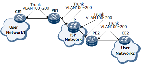
To connect VLAN 100 - VLAN 200 on User Network1 to VLAN 100 - VLAN 200 on User Network2, interfaces connecting CE1, PE1, the P, PE2, and CE2 can be configured to function as trunk interfaces and to allow packets from VLAN 100 - VLAN 200 to pass through.
This configuration, however, makes user VLANs visible on the backbone network and wastes the carrier's VLAN ID resources (4094 VLAN IDs are used). In addition, the carrier has to manage user VLAN IDs, and users do not have the right to plan their own VLANs.
The 12-bit VLAN tag defined in IEEE 802.1Q identifies only a maximum of 4096 VLANs, unable to isolate and identify mass users in the growing metro Ethernet (ME) network. QinQ is therefore developed to expand the VLAN space by adding another 802.1Q tag to an 802.1Q tagged packet. In this way, the number of VLANs increases to 4096 x 4096.
Since the QinQ technology is easy to use, it has been widely applied on ISP networks. For example, it is used by multiple services on the metro Ethernet.After the emergence of selective QinQ (VLAN stacking), QinQ services became popular with carriers. With selective QinQ, private VLANs and the public VLAN can be separated, and VLAN ID resources can be saved for carrier networks. As the metro Ethernet develops, different vendors propose their own metro Ethernet solutions. QinQ with its simplicity and flexibility, plays important roles in metro Ethernet solutions.
QinQ Definition
802.1Q-in-802.1Q (QinQ) is a technology that adds another layer of IEEE 802.1Q tag to the 802.1Q tagged packets entering the network. This technology expands the VLAN space by tagging the tagged packets. It allows services in a private VLAN to be transparently transmitted over a public network.
Figure 2 shows a typical QinQ application. The private VLANs on User Network 1 range from VLAN 100 to VLAN 200, and the private VLANs on User Network 2 range from VLAN 400 to VLAN 500. If a carrier allows VLAN users to communicate over the carrier network, the carrier must assign a different VLAN ID for each VLAN. This requires a large number of VLAN IDs, and user packets are made visible on the carrier network. QinQ allows a network to have a maximum of 4094 x 4094 VLAN IDs. With QinQ, the carrier only needs to provide one VLAN ID for a user network, which saves VLAN ID resources and ensures secure transmission of user packets.
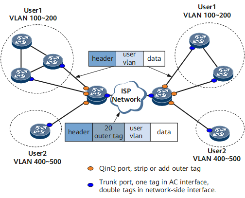
Figure 2 shows a typical QinQ application. VLAN stacking is a typical application of QinQ on Layer 2 networks.
The advantages of QinQ are described as follows:
- Alleviates the intensifying shortage of public VLAN IDs.
- Allows users to plan their private VLAN IDs and prevents conflicts with public VLAN IDs.
- Provides a simple, flexible Layer 2 VPN solution for small-scale Metropolitan Area Networks (MANs) or the Local Area Networks (LANs).
- Allows user networks to retain their configurations after a carrier updates the carrier network.
Basic QinQ Concept
Ethernet Frame, VLAN Frame, and QinQ PacketEthernet frame
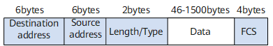
As shown in Figure 3, the Length/Type field is preceded by the Destination address and Source address fields in a traditional Ethernet frame.
VLAN frame
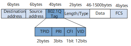
IEEE 802.1Q adds an 802.1Q tag to the Ethernet frame. As shown in Figure 4, the 4-byte 802.1Q Tag resides between the Source address and Length/Type fields.
Type: The 2-byte Type field indicates the frame type. The value 0x8100 indicates an 802.1Q frame. When a device that does not support 802.1Q frames receives an 802.1Q frame, it discards the frame.
PRI: The 3-bit Priority field indicates the frame priority. The value of the field ranges from 0 to 7. The greater the value, the higher the frame priority. When a switch is congested, higher priority frames are sent preferentially.
CFI: The 1-bit Canonical Format Indicator (CFI) field indicates whether the MAC address is in canonical format: 0 indicates that the MAC address is in canonical format, 1 indicates that it is not. This field is used to differentiate Ethernet frames, Fiber Distributed Digital Interface (FDDI) frames, and token ring frames. The CFI field value in Ethernet frames is 0.
VID: The 12-bit VLAN ID (VID) field indicates the VLAN to which the frame belongs. In the NetEngine 8000 F, the VLAN ID ranges from 0 to 4095. Since 0 and 4095 are reserved by the QinQ protocol, the valid value of the VLAN ID ranges from 1 to 4094.
Each 802.1Q-capable switch sends datagrams carrying a VLAN ID. The VLAN ID identifies the VLAN to which the switch belongs. Ethernet frames can be classified into the following types on a VLAN:- Tagged frame: Ethernet frame with a 4-byte 802.1Q tag.
- Untagged frame: original Ethernet frame without a 4-byte 802.1Q tag.
QinQ packet
A QinQ packet has a fixed format. In the packet, another 802.1Q tag is added before an 802.1Q tag. A QinQ packet is 4–byte longer than a common 802.1Q packet.
Figure 5 QinQ packet format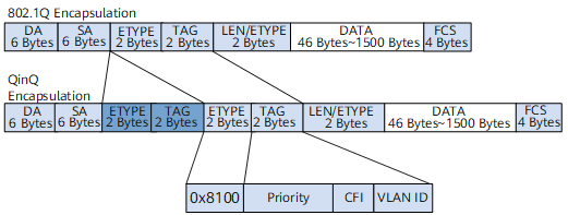 QinQ packets carry two VLAN tags when they are transmitted across a carrier network. The meanings of the two tags are described as follows:
- Inner VLAN tag: private VLAN tag that identifies the VLAN to which a user belongs.
- Outer VLAN tag: public VLAN tag that is assigned by a carrier to a user.
QinQ Encapsulation
QinQ encapsulation is to add another 802.1Q tag to a single-tagged packet. QinQ encapsulation is usually performed on UPE interfaces connecting to users.
QinQ encapsulation can be classified into the following types:
Standard QinQ encapsulation
In a standard QinQ encapsulation, or interface-based QinQ, the device adds an outer tag to all packets entering an interface.
After a QinQ-enabled interface receives a packet, the device adds the default VLAN tag to the packet, regardless of whether the packet carries a VLAN tag. The packet is then forwarded in the VLAN to which the interface belongs. Interface-based QinQ is also called QinQ tunneling.
Interface-based QinQ means that all traffic entering an interface is encapsulated with the same outer VLAN tag. Users are distinguished by the physical interface. However, if multiple users with different VLANs are connected to the same interface, the device cannot distinguish these users. Therefore, interface-based QinQ has its limitations.
For carrier networks that need to distinguish users based on user applications and locations, the selective QinQ provides an ideal solution.
Selective QinQ encapsulation
The selective QinQ encapsulation is also called traffic-based QinQ because the device encapsulates packets with outer tags based on the traffic.
After a selective QinQ-enabled interface receives packets, the device classifies the traffic and decides whether to add outer tags to the packets.
A carrier device can classify traffic based private VLAN tags, VLAN tag+802.1p priority, source IP/MAC address, destination IP/MAC address, IP protocols, or application port numbers. The device then adds outer VLAN tags to the traffic for service differentiation.
Sub-interface for VLAN Tag Termination
- After an interface receives a packet with one or two VLAN tags, the device removes the VLAN tags and forwards the packet at Layer 3. The outbound interface decides whether to add one or two VLAN tags to the packet.
- Before an interface forwards a packet, the device adds the planned VLAN tag to the packet.
The following section describes the termination types, the VLAN tag termination sub-interfaces, and the applications of VLAN tag termination.
-
VLAN packets are classified into dot1q packets, which carry only one VLAN tag, and QinQ packets, which carry two VLAN tags. Accordingly, there are two VLAN tag termination modes:
VLAN tag termination sub-interfaces
Dot1q/QinQ termination is conducted on sub-interfaces.Sub-interface for dot1q VLAN tag termination
A sub-interface that terminates packets carrying one VLAN tag.
Sub-interface for QinQ VLAN tag termination
A sub-interface that terminates packets carrying two VLAN tags.
Sub-interfaces for QinQ VLAN tag termination are classified into the following types:- Explicit sub-interface for QinQ VLAN tag termination: The pair of VLAN tags specifies two VLANs.
- Implicit sub-interface for QinQ VLAN tag termination: The pair of VLAN tags specifies two ranges of VLANs.

Dot1q and QinQ VLAN tag termination sub-interfaces do not support transparent transmission of packets that do not contain a VLAN tag, and discard received packets that do not contain a VLAN tag.
- Applications of VLAN tag termination
-
The VLAN technology is widely used because it allows Layer 2 packets of different users to be transmitted separately. With the VLAN technology, a physical LAN is divided into multiple logical broadcast domains (VLANs). Hosts in the same VLAN can communicate with each other at Layer 2, but hosts in different VLANs cannot. The Layer 3 routing technology is required for communication between hosts in different VLANs. The following interfaces can be used to implement inter-VLAN communication:
Layer 3 Ethernet interfaces on routers
Conventional Layer 3 Ethernet interfaces do not identify VLAN packets. After receiving VLAN packets, they consider the packets invalid and discard them. To implement inter-VLAN communication, create Ethernet sub-interfaces on an Ethernet interface and configure the sub-interfaces to remove tags from VLAN packets.
Communication between devices in the LAN and WAN
Most LAN packets carry VLAN tags. Certain wide area network (WAN) protocols, such as Point-to-Point Protocol (PPP), cannot identify VLAN packets. Before forwarding VLAN packets from a LAN to a WAN, a device needs to record the VLAN information carried in the VLAN packets and then remove the VLAN tags.
When a device receives packets, it adds the locally stored VLAN information to the packets and forwards them to VLAN users.
-