Example for Configuring a QinQ VLAN Tag Termination Sub-Interface to Support VRRP
This section describes how to ensure reliable and stable connections between users that send double-tagged packets and the network after you have configured a QinQ VLAN tag termination sub-interface to support VRRP (Virtual Router Redundancy Protocol).
Networking Requirements
To use VLAN tag termination sub-interfaces to access a network with a VRRP group, enable VRRP on the sub-interfaces. VRRP can ensure reliable and stable communication between users on the network.
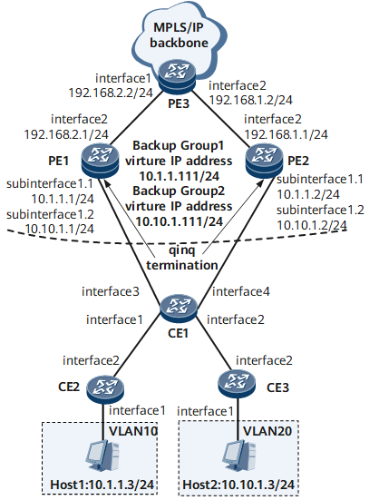
On the network shown in Figure 1, packets sent by the CEs to the PEs carry two VLAN tags, and the CEs are connected to the network with VRRP groups using QinQ VLAN tag termination sub-interfaces. To ensure that a master/backup VRRP switchover is performed immediately after a fault occurs on the network and that the communication is reliable and stable, configure QinQ VLAN tag termination sub-interfaces to support VRRP.
Configuration Roadmap
The configuration roadmap is as follows:
Create VLANs on CE2 and CE3 and determine the VLANs to which users belong.
Enable QinQ on CE1 so that packets sent by CE1 to PE1 and PE2 carry two VLAN tags.
Configure two VRRP groups on both PE1 and PE2 to implement link backup and load balancing.
Configure QinQ VLAN tag termination sub-interfaces on PE1 and PE2 to support VRRP to ensure stable network communication.
Configure a routing protocol on PE1, PE2, and PE3 to ensure that users can access the carrier network on the Layer 3 network.
Open Shortest Path First (OSPF) is used in this example.
Data Preparation
To complete the configuration, you need the following data:
- Users' VLAN IDs and IP addresses
- VLAN IDs in the outer VLAN tags of packets sent by CE1 to PE1 and PE2.
- Names and IP addresses of the interfaces that connect PE1 and PE2 to CE1.
- Names and IP addresses of the interfaces that connect PE1 and PE2
- IDs and virtual IP addresses of VRRP groups and priorities of PE1 and PE2 in the VRRP groups
Procedure
- Create VLANs on CE2 and CE3 and associate Layer 2 interfaces with the VLANs.
# Configure CE2.
<HUAWEI> system-view
[~HUAWEI] sysname CE2
[*HUAWEI] commit
[~CE2] vlan 10
[*CE2-vlan10] quit
[*CE2] interface gigabitethernet 0/1/1
[*CE2-GigabitEthernet0/1/1] undo shutdown
[*CE2-GigabitEthernet0/1/1] portswitch
[*CE2-GigabitEthernet0/1/1] port link-type access
[*CE2-GigabitEthernet0/1/1] port default vlan 10
[*CE2-GigabitEthernet0/1/1] quit
[*CE2] interface gigabitethernet 0/1/2
[*CE2-GigabitEthernet0/1/2] undo shutdown
[*CE2-GigabitEthernet0/1/2] portswitch
[*CE2-GigabitEthernet0/1/2] port link-type trunk
[*CE2-GigabitEthernet0/1/2] port trunk allow-pass vlan 10
[*CE2-GigabitEthernet0/1/2] quit
[*CE2] commit
# Configure CE3.
<HUAWEI> system-view
[~HUAWEI] sysname CE3
[*HUAWEI] commit
[~CE3] vlan 20
[*CE3-vlan20] quit
[*CE3] interface gigabitethernet 0/1/1
[*CE3-GigabitEthernet0/1/1] undo shutdown
[*CE3-GigabitEthernet0/1/1] portswitch
[*CE3-GigabitEthernet0/1/1] port link-type access
[*CE3-GigabitEthernet0/1/1] port default vlan 20
[*CE3-GigabitEthernet0/1/1] quit
[*CE3] interface gigabitethernet 0/1/2
[*CE3-GigabitEthernet0/1/2] undo shutdown
[*CE3-GigabitEthernet0/1/2] portswitch
[*CE3-GigabitEthernet0/1/2] port link-type trunk
[*CE3-GigabitEthernet0/1/2] port trunk allow-pass vlan 20
[*CE3-GigabitEthernet0/1/2] quit
[*CE3] commit

If the interface is already a Layer 2 interface, do not run the portswitch command.
- Enable QinQ on CE1.
<HUAWEI> system-view
[~HUAWEI] sysname CE1
[*HUAWEI] commit
[~CE1] vlan 100
[*CE1-vlan100] quit
[*CE1] interface gigabitethernet 0/1/1
[*CE1-GigabitEthernet0/1/1] undo shutdown
[*CE1-GigabitEthernet0/1/1] portswitch
[*CE1-GigabitEthernet0/1/1] port vlan-stacking vlan 10 stack-vlan 100
[*CE1-GigabitEthernet0/1/1] quit
[*CE1] interface gigabitethernet 0/1/2
[*CE1-GigabitEthernet0/1/2] undo shutdown
[*CE1-GigabitEthernet0/1/2] portswitch
[*CE1-GigabitEthernet0/1/2] port vlan-stacking vlan 20 stack-vlan 100
[*CE1-GigabitEthernet0/1/2] quit
[*CE1] interface gigabitethernet 0/1/3
[*CE1-GigabitEthernet0/1/3] undo shutdown
[*CE1-GigabitEthernet0/1/3] portswitch
[*CE1-GigabitEthernet0/1/3] port link-type trunk
[*CE1-GigabitEthernet0/1/3] port trunk allow-pass vlan 100
[*CE1-GigabitEthernet0/1/3] quit
[*CE1] interface gigabitethernet 0/1/4
[*CE1-GigabitEthernet0/1/4] undo shutdown
[*CE1-GigabitEthernet0/1/4] portswitch
[*CE1-GigabitEthernet0/1/4] port link-type trunk
[*CE1-GigabitEthernet0/1/4] port trunk allow-pass vlan 100
[*CE1-GigabitEthernet0/1/4] quit
[*CE1] commit
If the device does not support the port vlan-stacking command, you can run the port link-type dot1q-tunnel command and port default vlan command on the interface to configure the QinQ function.
- Configure VRRP groups.
# Create VRRP group 1 and VRRP group 2 on PE1, set the VRRP priority to 120 for PE1 in VRRP group 1 so that PE1 is the Master in VRRP group 1 and the Backup in VRRP group 2.
<HUAWEI> system-view
[~HUAWEI] sysname PE1
[*HUAWEI] commit
[~PE1] interface gigabitethernet 0/1/1
[*PE1-GigabitEthernet0/1/1] undo shutdown
[*PE1] interface gigabitethernet 0/1/1.1
[*PE1-GigabitEthernet0/1/1.1] vrrp vrid 1 virtual-ip 10.1.1.111
[*PE1-GigabitEthernet0/1/1.1] vrrp vrid 1 priority 120
[*PE1-GigabitEthernet0/1/1.1] vrrp vrid 1 preempt-mode timer delay 20
[*PE1-GigabitEthernet0/1/1.1] vrrp recover-delay 20
[*PE1-GigabitEthernet0/1/1.1] ip address 10.1.1.1 24
[*PE1-GigabitEthernet0/1/1.1] arp broadcast enable
[*PE1-GigabitEthernet0/1/1.1] quit
[*PE1] interface gigabitethernet 0/1/1.2
[*PE1-GigabitEthernet0/1/1.2] vrrp vrid 2 virtual-ip 10.10.1.111
[*PE1-GigabitEthernet0/1/1.2] ip address 10.10.1.1 24
[*PE1-GigabitEthernet0/1/1.2] arp broadcast enable
[*PE1-GigabitEthernet0/1/1.2] quit
[*PE1] commit
# Create VRRP group 1 and VRRP group 2 on PE2, set the VRRP priority to 120 for PE2 in VRRP group 2 so that PE2 is the Master in VRRP group 2 and the Backup in VRRP group 1.
<HUAWEI> system-view
[~HUAWEI] sysname PE2
[*HUAWEI] commit
[~PE2] interface gigabitethernet 0/1/1
[*PE2-GigabitEthernet0/1/1] undo shutdown
[*PE2] interface gigabitethernet 0/1/1.1
[*PE2-GigabitEthernet0/1/1.1] vrrp vrid 1 virtual-ip 10.1.1.111
[*PE2-GigabitEthernet0/1/1.1] ip address 10.1.1.2 24
[*PE2-GigabitEthernet0/1/1.1] arp broadcast enable
[*PE2-GigabitEthernet0/1/1.1] quit
[*PE2] interface gigabitethernet 0/1/1.2
[*PE2-GigabitEthernet0/1/1.2] vrrp vrid 2 virtual-ip 10.10.1.111
[*PE2-GigabitEthernet0/1/1.2] vrrp vrid 2 priority 120
[*PE2-GigabitEthernet0/1/1.2] vrrp vrid 2 preempt-mode timer delay 20
[*PE2-GigabitEthernet0/1/1.2] vrrp recover-delay 20
[*PE2-GigabitEthernet0/1/1.2] ip address 10.10.1.2 24
[*PE2-GigabitEthernet0/1/1.2] arp broadcast enable
[*PE2-GigabitEthernet0/1/1.2] quit
[*PE2] commit
- Configure QinQ VLAN tag termination sub-interfaces to support VRRP.
# Configure PE1.
[~PE1] interface gigabitethernet 0/1/1.1
[*PE1-GigabitEthernet0/1/1.1] control-vid 1 qinq-termination
[*PE1-GigabitEthernet0/1/1.1] qinq termination pe-vid 100 ce-vid 10
[*PE1-GigabitEthernet0/1/1.1] qinq vrrp pe-vid 100 ce-vid 10
[*PE1-GigabitEthernet0/1/1.1] arp broadcast enable
[*PE1-GigabitEthernet0/1/1.1] quit
[*PE1-GigabitEthernet0/1/1.2] control-vid 2 qinq-termination
[*PE1-GigabitEthernet0/1/1.2] qinq termination pe-vid 100 ce-vid 20
[*PE1-GigabitEthernet0/1/1.2] qinq vrrp pe-vid 100 ce-vid 20
[*PE1-GigabitEthernet0/1/1.2] arp broadcast enable
[*PE1-GigabitEthernet0/1/1.2] quit
[*PE1] commit
# Configure PE2.
[~PE2] interface gigabitethernet 0/1/1.1
[*PE2-GigabitEthernet0/1/1.1] control-vid 1 qinq-termination
[*PE2-GigabitEthernet0/1/1.1] qinq termination pe-vid 100 ce-vid 10
[*PE2-GigabitEthernet0/1/1.1] qinq vrrp pe-vid 100 ce-vid 10
[*PE2-GigabitEthernet0/1/1.1] arp broadcast enable
[*PE2-GigabitEthernet0/1/1.1] quit
[*PE2-GigabitEthernet0/1/1.2] control-vid 2 qinq-termination
[*PE2-GigabitEthernet0/1/1.2] qinq termination pe-vid 100 ce-vid 20
[*PE2-GigabitEthernet0/1/1.2] qinq vrrp pe-vid 100 ce-vid 20
[*PE2-GigabitEthernet0/1/1.2] arp broadcast enable
[*PE2-GigabitEthernet0/1/1.2] quit
[*PE2] commit
After the configurations are complete, run the display vrrp command on PE1. The command output shows that PE1 is Master in VRRP group 1 and Backup in VRRP group 2. Run the display vrrp command on PE2. The command output shows that PE2 is Master in VRRP group 2 and Backup in VRRP group 1.
[~PE1] display vrrp
GigabitEthernet0/1/1.1 | Virtual Router 1
State          : Master
Virtual IP     : 10.1.1.111
Master IP      : 10.1.1.1
Local IP       : 10.1.1.1
PriorityRun    : 120
PriorityConfig : 120
MasterPriority : 120
Preempt        : YES   Delay Time : 20s
Hold Multiplier:4
TimerRun       : 1s
TimerConfig    : 1s
Auth Type      : NONE
Virtual MAC    : 00e0-fc12-3456
Check TTL      : YES
Config Type    : normal-vrrp
Create Time       : 2012-07-18 09:53:03
Last Change Time  : 2012-07-18 09:54:17

GigabitEthernet0/1/1.2 | Virtual Router 2
State          : Backup
Virtual IP     : 10.10.1.111
Master IP      : 10.10.1.2
Local IP       : 10.10.1.2
PriorityRun    : 100
PriorityConfig : 100
MasterPriority : 120
Preempt        : YES   Delay Time : 0s
Hold Multiplier:4
TimerRun       : 1s
TimerConfig    : 1s
Auth Type      : NONE
Virtual MAC    : 00e0-fc12-3457
Check TTL      : YES
Config Type    : normal-vrrp
Create Time       : 2012-07-18 09:53:03
Last Change Time  : 2012-07-18 09:56:33
[~PE2] display vrrp
GigabitEthernet0/1/1.1 | Virtual Router 1
State          : Backup
Virtual IP     : 10.1.1.111
Master IP      : 10.1.1.1
Local IP       : 10.1.1.2
PriorityRun    : 100
PriorityConfig : 100
MasterPriority : 120
Preempt        : YES   Delay Time : 0s
Hold Multiplier:4
TimerRun       : 1s
TimerConfig    : 1s
Auth Type      : NONE
Virtual MAC    : 00e0-fc12-3456
Check TTL      : YES
Config Type    : normal-vrrp
Create Time       : 2012-07-18 09:53:00
Last Change Time  : 2012-07-18 09:56:11

GigabitEthernet0/1/1.2 | Virtual Router 2
State          : Master
Virtual IP     : 10.10.1.111
Master IP      : 10.10.1.2
Local IP       : 10.10.1.2
PriorityRun    : 120
PriorityConfig : 120
MasterPriority : 120
Preempt        : YES   Delay Time : 20s
Hold Multiplier:4
TimerRun       : 1s
TimerConfig    : 1s
Auth Type      : NONE
Virtual MAC    : 00e0-fc12-3457
Check TTL      : YES
Config Type    : normal-vrrp
Create Time       : 2012-07-18 09:53:00
Last Change Time  : 2012-07-18 09:56:33
Run the shutdown command on GE 0/1/1.1 of PE1 to simulate a situation in which PE1 is faulty.
Run the display vrrp command on PE1 and PE2 to view the VRRP status. The command outputs show that the VRRP status of PE1 is Initialize and the VRRP status of PE2 is Master.
[~PE1] display vrrp
GigabitEthernet0/1/1.1 | Virtual Router 1
State          : Initialize
Virtual IP     : 10.1.1.111
Master IP      : 0.0.0.0
Local IP       : 10.1.1.1
PriorityRun    : 120
PriorityConfig : 120
MasterPriority : 0
Preempt        : YES   Delay Time : 20s
Hold Multiplier:4
TimerRun       : 1s
TimerConfig    : 1s
Auth Type      : NONE
Virtual MAC    : 00e0-fc12-3456
Check TTL      : YES
Config Type    : normal-vrrp
Create Time       : 2012-07-18 09:53:03
Last Change Time  : 2012-07-18 10:03:03

GigabitEthernet0/1/1.2 | Virtual Router 2
State          : Backup
Virtual IP     : 10.10.1.111
Master IP      : 10.10.1.2
Local IP       : 10.10.1.1
PriorityRun    : 100
PriorityConfig : 100
MasterPriority : 120
Preempt        : YES   Delay Time : 0s
Hold Multiplier:4
TimerRun       : 1s
TimerConfig    : 1s
Auth Type      : NONE
Virtual MAC    : 00e0-fc12-3457
Check TTL      : YES
Config Type    : normal-vrrp
Create Time       : 2012-07-18 09:53:03
Last Change Time  : 2012-07-18 09:56:33
[*PE2] display vrrp
GigabitEthernet0/1/1.1 | Virtual Router 1
State          : Master
Virtual IP     : 10.1.1.111
Master IP      : 10.1.1.2
Local IP       : 10.1.1.2
PriorityRun    : 100
PriorityConfig : 100
MasterPriority : 100
Preempt        : YES   Delay Time : 0s
Hold Multiplier:4
TimerRun       : 1s
TimerConfig    : 1s
Auth Type      : NONE
Virtual MAC    : 00e0-fc12-3456
Check TTL      : YES
Config Type    : normal-vrrp
Create Time       : 2012-07-18 09:53:00
Last Change Time  : 2012-07-18 10:53:09

GigabitEthernet0/1/1.2 | Virtual Router 2
State          : Master
Virtual IP     : 10.10.1.111
Master IP      : 10.10.1.2
Local IP       : 10.10.1.2
PriorityRun    : 120
PriorityConfig : 120
MasterPriority : 120
Preempt        : YES   Delay Time : 20s
Hold Multiplier:4
TimerRun       : 1s
TimerConfig    : 1s
Auth Type      : NONE
Virtual MAC    : 00e0-fc12-3457
Check TTL      : YES
Config Type    : normal-vrrp
Create Time       : 2012-07-18 09:53:00
Last Change Time  : 2012-07-18 09:56:33
Run the undo shutdown command on GE 0/1/1.1 on PE1. After GE 0/1/1.1 goes Up, run the display vrrp command on PE1 to view the VRRP status. The command output shows that the VRRP status of PE1 is Backup.
- If no preemption delay is configured in VRRP group 1, the VRRP status of PE1 is Master immediately.
- If the preemption delay is configured in VRRP group 1, the VRRP status of PE1 is Master after 20 seconds.
[~PE1] display vrrp
GigabitEthernet0/1/1.1 | Virtual Router 1
State          : Backup
Virtual IP     : 10.1.1.111
Master IP      : 10.1.1.2
Local IP       : 10.1.1.1
PriorityRun    : 120
PriorityConfig : 120
MasterPriority : 100
Preempt        : YES   Delay Time : 20s
Hold Multiplier:4
TimerRun       : 1s
TimerConfig    : 1s
Auth Type      : NONE
Virtual MAC    : 00e0-fc12-3456
Check TTL      : YES
Config Type    : normal-vrrp
Create Time       : 2012-07-18 09:53:03
Last Change Time  : 2012-07-18 10:54:35

GigabitEthernet0/1/1.2 | Virtual Router 2
State          : Backup
Virtual IP     : 10.10.1.111
Master IP      : 10.10.1.2
Local IP       : 10.10.1.1
PriorityRun    : 100
PriorityConfig : 100
MasterPriority : 120
Preempt        : YES   Delay Time : 0s
Hold Multiplier:4
TimerRun       : 1s
TimerConfig    : 1s
Auth Type      : NONE
Virtual MAC    : 00e0-fc12-3457
Check TTL      : YES
Config Type    : normal-vrrp
Create Time       : 2012-07-18 09:53:03
Last Change Time  : 2012-07-18 09:56:33
After 20 seconds, run the display vrrp command on PE1 to view the VRRP status. The command output shows that the VRRP status of PE1 is Master.
[*PE1] display vrrp
GigabitEthernet0/1/1.1 | Virtual Router 1
State          : Master
Virtual IP     : 10.1.1.111
Master IP      : 10.1.1.1
Local IP       : 10.1.1.1
PriorityRun    : 120
PriorityConfig : 120
MasterPriority : 120
Preempt        : YES   Delay Time : 20s
Hold Multiplier:4
TimerRun       : 1s
TimerConfig    : 1s
Auth Type      : NONE
Virtual MAC    : 00e0-fc12-3456
Check TTL      : YES
Config Type    : normal-vrrp
Create Time       : 2012-07-18 09:53:03
Last Change Time  : 2012-07-18 10:54:50

GigabitEthernet0/1/1.2 | Virtual Router 2
State          : Backup
Virtual IP     : 10.10.1.111
Master IP      : 10.10.1.2
Local IP       : 10.10.1.1
PriorityRun    : 100
PriorityConfig : 100
MasterPriority : 120
Preempt        : YES   Delay Time : 0s
Hold Multiplier:4
TimerRun       : 1s
TimerConfig    : 1s
Auth Type      : NONE
Virtual MAC    : 00e0-fc12-3457
Check TTL      : YES
Config Type    : normal-vrrp
Create Time       : 2012-07-18 09:53:03
Last Change Time  : 2012-07-18 09:56:33
- Configure OSPF on the PEs.
Configure IP addresses of interfaces and OSPF on the PEs, as shown in Figure 1.
# Configure PE1.
[*PE1] interface gigabitethernet0/1/2
[*PE1-GigabitEthernet0/1/2] undo shutdown
[*PE1-GigabitEthernet0/1/2] ip address 192.168.2.1 24
[*PE1-GigabitEthernet0/1/2] quit
[*PE1] ospf
[*PE1-ospf-1] area 0
[*PE1-ospf-1-area-0.0.0.0] network 192.168.2.0 0.0.0.255
[*PE1-ospf-1-area-0.0.0.0] network 10.1.1.0 0.0.0.255
[*PE1-ospf-1-area-0.0.0.0] network 10.10.1.0 0.0.0.255
[*PE1-ospf-1-area-0.0.0.0] quit
[*PE1-ospf-1] quit
[*PE1] commit
# Configure PE2.
[~PE2] interface gigabitethernet0/1/2
[*PE2-GigabitEthernet0/1/2] undo shutdown
[*PE2-GigabitEthernet0/1/2] ip address 192.168.1.1 24
[*PE2-GigabitEthernet0/1/2] quit
[*PE2] ospf
[*PE2-ospf-1] area 0
[*PE2-ospf-1-area-0.0.0.0] network 192.168.1.0 0.0.0.255
[*PE2-ospf-1-area-0.0.0.0] network 10.1.1.0 0.0.0.255
[*PE2-ospf-1-area-0.0.0.0] network 10.10.1.0 0.0.0.255
[*PE2-ospf-1-area-0.0.0.0] quit
[*PE2-ospf-1] quit
[*PE2] commit
# Configure PE3.
<HUAWEI> system-view
[~HUAWEI] sysname PE3
[*HUAWEI] commit
[~PE3] interface gigabitethernet0/1/1
[*PE3-GigabitEthernet0/1/1] undo shutdown
[*PE3-GigabitEthernet0/1/1] ip address 192.168.2.2 24
[*PE3-GigabitEthernet0/1/1] quit
[*PE3] interface gigabitethernet 0/1/2
[*PE3-GigabitEthernet0/1/2] undo shutdown
[*PE3-GigabitEthernet0/1/2] ip address 192.168.1.2 24
[*PE3-GigabitEthernet0/1/2] quit
[*PE3] ospf
[*PE3-ospf-1] area 0
[*PE3-ospf-1-area-0.0.0.0] network 192.168.1.0 0.0.0.255
[*PE3-ospf-1-area-0.0.0.0] network 192.168.2.0 0.0.0.255
[*PE3-ospf-1-area-0.0.0.0] quit
[*PE3-ospf-1] quit
[*PE3] commit
After the configurations are complete, PE1 and PE2 can ping each other.
Use the command output on PE1 as an example.
[~PE1] ping 192.168.1.1 PING 192.168.1.1: 56 data bytes, press CTRL_C to break Reply from 192.168.1.1: bytes=56 Sequence=1 ttl=255 time=140 ms Reply from 192.168.1.1: bytes=56 Sequence=2 ttl=255 time=23 ms Reply from 192.168.1.1: bytes=56 Sequence=3 ttl=255 time=56 ms Reply from 192.168.1.1: bytes=56 Sequence=4 ttl=255 time=14 ms Reply from 192.168.1.1: bytes=56 Sequence=5 ttl=255 time=4 ms --- 192.168.1.1 ping statistics --- 5 packet(s) transmitted 5 packet(s) received 0.00% packet loss round-trip min/avg/max = 4/47/140 ms - Verify the configuration.
Run the display ip routing-table command on PE1 and PE2. Verify that the following conditions are true:
a. The command outputs show that there is a direct route in the routing table of PE1.
b. The destination address of the direct route is a virtual IP address.
c. The route to the same destination address on PE2 is an OSPF route.
[*PE1] display ip routing-table
Route Flags: R - relay, D - download to fib, T - to vpn-instance, B - black hole route
------------------------------------------------------------------------------
Routing Table : _public_
         Destinations : 16       Routes : 16

Destination/Mask    Proto  Pre  Cost        Flags NextHop         Interface

       10.1.1.0/24  Direct 0    0             D  10.1.1.1        GigabitEthernet0/1/1.1
       10.1.1.1/32  Direct 0    0             D  127.0.0.1       GigabitEthernet0/1/1.1
     10.1.1.111/32  Direct 0    0             D  127.0.0.1       GigabitEthernet0/1/1.1
     10.1.1.255/32  Direct 0    0             D  127.0.0.1       GigabitEthernet0/1/1.1
       127.0.0.0/8  Direct 0    0             D  127.0.0.1       InLoopBack0
      127.0.0.1/32  Direct 0    0             D  127.0.0.1       InLoopBack0
127.255.255.255/32  Direct 0    0             D  127.0.0.1       InLoopBack0
    192.168.1.0/24  OSPF   10   2             D  10.10.1.2       GigabitEthernet0/1/1.2
                    OSPF   10   2             D  10.1.1.2        GigabitEthernet0/1/1.1
                    OSPF   10   2             D  192.168.2.2     GigabitEthernet0/1/2
    192.168.2.0/24  Direct 0    0             D  192.168.2.1     GigabitEthernet0/1/2
    192.168.2.1/32  Direct 0    0             D  127.0.0.1       GigabitEthernet0/1/2
  192.168.2.255/32  Direct 0    0             D  127.0.0.1       GigabitEthernet0/1/2
      10.10.1.0/24  Direct 0    0             D  10.10.1.1       GigabitEthernet0/1/1.2
      10.10.1.1/32  Direct 0    0             D  127.0.0.1       GigabitEthernet0/1/1.2
    10.10.1.111/32  OSPF   10   2             D  10.10.1.2       GigabitEthernet0/1/1.2
                    OSPF   10   2             D  10.1.1.2        GigabitEthernet0/1/1.1
    10.10.1.255/32  Direct 0    0             D  127.0.0.1       GigabitEthernet0/1/1.2
255.255.255.255/32  Direct 0    0             D  127.0.0.1       InLoopBack0
[~PE2] display ip routing-table
Route Flags: R - relay, D - download to fib, T - to vpn-instance, B - black hole route
------------------------------------------------------------------------------
Routing Table : _public_
         Destinations : 16       Routes : 16

Destination/Mask    Proto  Pre  Cost        Flags NextHop         Interface

       10.1.1.0/24  Direct 0    0             D  10.1.1.2        GigabitEthernet0/1/1.1
       10.1.1.2/32  Direct 0    0             D  127.0.0.1       GigabitEthernet0/1/1.1
     10.1.1.111/32  OSPF   10   2             D  10.10.1.1       GigabitEthernet0/1/1.2
                    OSPF   10   2             D  10.1.1.1        GigabitEthernet0/1/1.1
     10.1.1.255/32  Direct 0    0             D  127.0.0.1       GigabitEthernet0/1/1.1
       127.0.0.0/8  Direct 0    0             D  127.0.0.1       InLoopBack0
      127.0.0.1/32  Direct 0    0             D  127.0.0.1       InLoopBack0
127.255.255.255/32  Direct 0    0             D  127.0.0.1       InLoopBack0
    192.168.1.0/24  Direct 0    0             D  192.168.1.1     GigabitEthernet0/1/2
    192.168.1.1/32  Direct 0    0             D  127.0.0.1       GigabitEthernet0/1/2
  192.168.1.255/32  Direct 0    0             D  127.0.0.1       GigabitEthernet0/1/2
    192.168.2.0/24  OSPF   10   2             D  10.10.1.1       GigabitEthernet0/1/1.2
                    OSPF   10   2             D  10.1.1.1        GigabitEthernet0/1/1.1
                    OSPF   10   2             D  192.168.1.2     GigabitEthernet0/1/2
      10.10.1.0/24  Direct 0    0             D  10.10.1.2       GigabitEthernet0/1/1.2
      10.10.1.2/32  Direct 0    0             D  127.0.0.1       GigabitEthernet0/1/1.2
    10.10.1.111/32  Direct 0    0             D  127.0.0.1       GigabitEthernet0/1/1.2
    10.10.1.255/32  Direct 0    0             D  127.0.0.1       GigabitEthernet0/1/1.2
255.255.255.255/32  Direct 0    0             D  127.0.0.1       InLoopBack0
Configuration Files
Configuration file of PE1
#
 sysname PE1
#
interface GigabitEthernet0/1/1
 undo shutdown
#
interface GigabitEthernet0/1/1.1
 ip address 10.1.1.1 255.255.255.0
 encapsulation qinq-termination
 qinq termination pe-vid 100 ce-vid 10
 qinq vrrp pe-vid 100 ce-vid 10
 arp broadcast enable
 vrrp vrid 1 virtual-ip 10.1.1.111
 vrrp vrid 1 priority 120
 vrrp vrid 1 preempt-mode timer delay 20
 vrrp recover-delay 20
#
interface GigabitEthernet0/1/1.2
 ip address 10.10.1.1 255.255.255.0
 encapsulation qinq-termination
 qinq termination pe-vid 100 ce-vid 20
 qinq vrrp pe-vid 100 ce-vid 20
 arp broadcast enable
 vrrp vrid 2 virtual-ip 10.10.1.111
#
interface GigabitEthernet0/1/2
 undo shutdown
 ip address 192.168.2.1 255.255.255.0
#
ospf 1
 area 0.0.0.0
  network 10.1.1.0 0.0.0.255
  network 192.168.2.0 0.0.0.255
  network 10.10.1.0 0.0.0.255
#
return
Configuration file of PE2
#
 sysname PE2
#
interface GigabitEthernet0/1/1
 undo shutdown
#
interface GigabitEthernet0/1/1.1
 ip address 10.1.1.2 255.255.255.0
 encapsulation qinq-termination
 qinq termination pe-vid 100 ce-vid 10
 qinq vrrp pe-vid 100 ce-vid 10
 arp broadcast enable
 vrrp vrid 1 virtual-ip 10.1.1.111
#
interface GigabitEthernet0/1/1.2
 ip address 10.10.1.2 255.255.255.0
 encapsulation qinq-termination
 qinq termination pe-vid 100 ce-vid 20
 qinq vrrp pe-vid 100 ce-vid 20
 arp broadcast enable
 vrrp vrid 2 virtual-ip 10.10.1.111
 vrrp vrid 2 priority 120
 vrrp vrid 2 preempt-mode timer delay 20
 vrrp recover-delay 20
#
interface GigabitEthernet0/1/2
 undo shutdown
 ip address 192.168.1.1 255.255.255.0
#
ospf 1
 area 0.0.0.0
  network 10.1.1.0 0.0.0.255
  network 192.168.1.0 0.0.0.255
  network 10.10.1.0 0.0.0.255
#
return
Configuration file of PE3
#
 sysname PE3
#
interface GigabitEthernet0/1/1
 undo shutdown
 ip address 192.168.2.2 255.255.255.0
#
interface GigabitEthernet0/1/2
 undo shutdown
 ip address 192.168.1.2 255.255.255.0
#
ospf 1
 area 0.0.0.0
  network 192.168.1.0 0.0.0.255
  network 192.168.2.0 0.0.0.255
#
return
Configuration file of CE1
#
 sysname CE1
#
 vlan batch 100
#
interface GigabitEthernet0/1/1
 portswitch
 undo shutdown
 port vlan-stacking vlan 10 stack-vlan 100
#
interface GigabitEthernet0/1/2
 portswitch
 undo shutdown
 port vlan-stacking vlan 20 stack-vlan 100
#
interface GigabitEthernet0/1/3
 portswitch
 undo shutdown
 port link-type trunk
 port trunk allow-pass vlan 100
#
interface GigabitEthernet0/1/4
 portswitch
 undo shutdown
 port link-type trunk
 port trunk allow-pass vlan 100
#
return
Configuration file of CE2
#
 sysname CE2
#
 vlan batch 10
#
interface GigabitEthernet0/1/1
 portswitch
 undo shutdown
 port link-type access
 port default vlan 10
#
interface GigabitEthernet0/1/2
 portswitch
 undo shutdown
 port link-type trunk
 port trunk allow-pass vlan 10
#
return
Configuration file of CE3
#
 sysname CE3
#
 vlan batch 20
#
interface GigabitEthernet0/1/1
 portswitch
 undo shutdown
 port link-type access
 port default vlan 20
#
interface GigabitEthernet0/1/2
 portswitch
 undo shutdown
 port link-type trunk
 port trunk allow-pass vlan 20
#
return