Example for Configuring a QinQ VLAN Tag Termination Sub-Interface to Access an L3VPN
This section describes how to configure a QinQ VLAN tag termination sub-interface to provide Layer 3 virtual private network (L3VPN) access and how to ensure that users communicate over the L3VPN using double-tagged packets.
Networking Requirements
When a VLAN tag termination sub-interface is used to access an L3VPN network, this sub-interface needs to be bound to a VPN instance to enable Layer 3 communication.
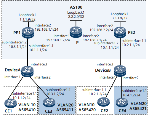
On the network shown in Figure 1, the CEs connect to the PEs through the routers, and the routers access the L3VPN through QinQ VLAN tag termination sub-interfaces. Packets sent by the routers to the PEs carry two VLAN tags. To ensure that user networks on which CE1 and CE2 reside can communicate and that user networks on which CE3 and CE4 reside can communicate, configure QinQ VLAN tag termination sub-interfaces on PE1 and PE2 and bind these sub-interfaces to virtual private network (VPN) instances to provide L3VPN access.
Configuration Roadmap
The configuration roadmap is as follows:
Configure the Layer 2 forwarding function on the CEs so that the packets sent by the CEs to the routers carry one VLAN tag.
Configure the QinQ and Layer 2 forwarding functions on Device A and Device B so that packets sent by Device A to PE1 and packets sent by Device B to PE2 carry two VLAN tags.
Configure L3VPN services on PE1, the P, and PE2, configure QinQ VLAN tag termination sub-interfaces on PE1 and PE2, and bind these sub-interfaces to VPN instances so that users can communicate over the L3VPN.
Configure a routing protocol on PE1, the P, and PE2 to ensure Layer 3 connectivity.
Open Shortest Path First (OSPF) is used in this example.
- Configure basic Multiprotocol Label Switching (MPLS) functions and MPLS Label Distribution Protocol (LDP) on PE1, the P, and PE2 and set up MPLS Label Switched Paths (LSPs) between these devices.
- Configure VPN instances and QinQ VLAN tag termination sub-interfaces on PE1 and PE2, bind these sub-interfaces to the VPN instances to provide L3VPN access.
- Establish a Multiprotocol Internal Border Gateway Protocol (MP-IBGP) peer relationship between the PEs so that users in the same VPN instance can communicate.
- Establish External BGP (EBGP) peer relationships between the PEs and CEs to exchange VPN routes so that the CEs can communicate.
Data Preparation
To complete the configuration, you need the following data:
- Users' VLAN IDs and IP addresses
- Names and IP addresses of the interfaces that connect the routers to the CEs
- VLAN IDs in the outer VLAN tags of packets sent by Device A to PE1 and packets sent by Device B to PE2
- Names and IP addresses of the interfaces that connect the PEs and the routers
- Names and IP addresses of the interfaces that connect PE1 and PE2
- MPLS LSR IDs of the PEs and P, names of VPN instances on the PEs, and VPN targets of VPN routes
Procedure
- Configure Layer 2 forwarding on the CEs.
# Configure CE1.
<HUAWEI> system-view
[~HUAWEI] sysname CE1
[*HUAWEI] commit
[~CE1] vlan 10
[*CE1-vlan10] quit
[*CE1] interface gigabitethernet 0/1/1
[*CE1-GigabitEthernet0/1/1] undo shutdown
[*CE1-GigabitEthernet0/1/1] quit
[*CE1] interface gigabitethernet 0/1/1.1
[*CE1-GigabitEthernet0/1/1.1] ip address 10.1.1.2 24
[*CE1-GigabitEthernet0/1/1.1] vlan-type dot1q 10
[*CE1-GigabitEthernet0/1/1.1] quit
[*CE1] commit
# Configure CE2.
<HUAWEI> system-view
[~HUAWEI] sysname CE2
[*HUAWEI] commit
[~CE2] vlan 10
[*CE2-vlan10] quit
[*CE2] interface gigabitethernet 0/1/1
[*CE2-GigabitEthernet0/1/1] undo shutdown
[*CE2-GigabitEthernet0/1/1] quit
[*CE2] interface gigabitethernet 0/1/1.1
[*CE2-GigabitEthernet0/1/1.1] ip address 10.2.1.2 24
[*CE2-GigabitEthernet0/1/1.1] vlan-type dot1q 10
[*CE2-GigabitEthernet0/1/1.1] quit
[*CE2] commit
# Configure CE3.
<HUAWEI> system-view
[~HUAWEI] sysname CE3
[*HUAWEI] commit
[~CE3] vlan 20
[*CE3-vlan20] quit
[*CE3] interface gigabitethernet 0/1/1
[*CE3-GigabitEthernet0/1/1] undo shutdown
[*CE3-GigabitEthernet0/1/1] quit
[*CE3] interface gigabitethernet 0/1/1.1
[*CE3-GigabitEthernet0/1/1.1] ip address 10.3.1.2 24
[*CE3-GigabitEthernet0/1/1.1] vlan-type dot1q 20
[*CE3-GigabitEthernet0/1/1.1] quit
[*CE3] commit
# Configure CE4.
<HUAWEI> system-view
[~HUAWEI] sysname CE4
[*HUAWEI] commit
[~CE4] vlan 20
[*CE4-vlan20] quit
[*CE4] interface gigabitethernet 0/1/1
[*CE4-GigabitEthernet0/1/1] undo shutdown
[*CE4-GigabitEthernet0/1/1] quit
[*CE4] interface gigabitethernet 0/1/1.1
[*CE4-GigabitEthernet0/1/1.1] ip address 10.4.1.2 24
[*CE4-GigabitEthernet0/1/1.1] vlan-type dot1q 20
[*CE4-GigabitEthernet0/1/1.1] quit
[*CE4] commit
- Configure the QinQ and Layer 2 forwarding functions on the routers.
# Configure Device A.
<HUAWEI> system-view
[~HUAWEI] sysname DeviceA
[*HUAWEI] commit
[~DeviceA] vlan 100
[*DeviceA-vlan100] quit
[*DeviceA] interface gigabitethernet 0/1/1
[*DeviceA-GigabitEthernet0/1/1] undo shutdown
[*DeviceA-GigabitEthernet0/1/1] portswitch
[*DeviceA-GigabitEthernet0/1/1] port vlan-stacking vlan 10 stack-vlan 100
[*DeviceA-GigabitEthernet0/1/1] quit
[*DeviceA] interface gigabitethernet 0/1/2
[*DeviceA-GigabitEthernet0/1/2] undo shutdown
[*DeviceA-GigabitEthernet0/1/2] portswitch
[*DeviceA-GigabitEthernet0/1/2] port vlan-stacking vlan 20 stack-vlan 100
[*DeviceA-GigabitEthernet0/1/2] quit
[*DeviceA] interface gigabitethernet 0/1/3
[*DeviceA-GigabitEthernet0/1/3] undo shutdown
[*DeviceA-GigabitEthernet0/1/3] portswitch
[*DeviceA-GigabitEthernet0/1/3] port link-type trunk
[*DeviceA-GigabitEthernet0/1/3] port trunk allow-pass vlan 100
[*DeviceA-GigabitEthernet0/1/3] quit
[*DeviceA] commit
# Configure Device B.
<HUAWEI> system-view
[~HUAWEI] sysname DeviceB
[*HUAWEI] commit
[~DeviceB] vlan 100
[*DeviceB-vlan100] quit
[*DeviceB] interface gigabitethernet 0/1/1
[*DeviceB-GigabitEthernet0/1/1] undo shutdown
[*DeviceB-GigabitEthernet0/1/1] portswitch
[*DeviceB-GigabitEthernet0/1/1] port vlan-stacking vlan 10 stack-vlan 100
[*DeviceB-GigabitEthernet0/1/1] quit
[*DeviceB] interface gigabitethernet 0/1/2
[*DeviceB-GigabitEthernet0/1/2] undo shutdown
[*DeviceB-GigabitEthernet0/1/2] portswitch
[*DeviceB-GigabitEthernet0/1/2] port vlan-stacking vlan 20 stack-vlan 100
[*DeviceB-GigabitEthernet0/1/2] quit
[*DeviceB] interface gigabitethernet 0/1/3
[*DeviceB-GigabitEthernet0/1/3] undo shutdown
[*DeviceB-GigabitEthernet0/1/3] portswitch
[*DeviceB-GigabitEthernet0/1/3] port link-type trunk
[*DeviceB-GigabitEthernet0/1/3] port trunk allow-pass vlan 100
[*DeviceB-GigabitEthernet0/1/3] quit
[*DeviceB] commit

If the device does not support the port vlan-stacking command, you can run the port link-type dot1q-tunnel command and port default vlan command on the interface to configure the QinQ function.
- Configure an L3VPN.
Configure OSPF on PE1, the P, and PE2.
Assign an IP address to each interface on the PEs and P. Make sure that the 32-bit loopback addresses of PE1, the P, and PE2 are advertised after OSPF is enabled.
# Configure PE1.
<HUAWEI> system-view
[~HUAWEI] sysname PE1
[*HUAWEI] commit
[~PE1] interface loopback 1
[*PE1-LoopBack1] ip address 1.1.1.9 32
[*PE1-LoopBack1] quit
[*PE1] interface gigabitethernet 0/1/2
[*PE1-GigabitEthernet0/1/2] ip address 192.168.1.1 24
[*PE1-GigabitEthernet0/1/2] undo shutdown
[*PE1-GigabitEthernet0/1/2] quit
[*PE1] ospf
[*PE1-ospf-1] area 0
[*PE1-ospf-1-area-0.0.0.0] network 1.1.1.9 0.0.0.0
[*PE1-ospf-1-area-0.0.0.0] network 192.168.1.0 0.0.0.255
[*PE1-ospf-1-area-0.0.0.0] quit
[*PE1-ospf-1] quit
[*PE1] commit
# Configure the P.
<HUAWEI> system-view
[~HUAWEI] sysname P
[*HUAWEI] commit
[~P] interface LoopBack 1
[*P-LoopBack1] ip address 2.2.2.9 32
[*P-LoopBack1] quit
[*P] interface gigabitethernet 0/1/1
[*P-GigabitEthernet0/1/1] ip address 192.168.1.2 24
[*P-GigabitEthernet0/1/1] undo shutdown
[*P-GigabitEthernet0/1/1] quit
[*P] interface gigabitethernet 0/1/2
[*P-GigabitEthernet0/1/2] ip address 192.168.2.1 24
[*P-GigabitEthernet0/1/2] undo shutdown
[*P-GigabitEthernet0/1/2] quit
[*P] ospf
[*P-ospf-1] area 0
[*P-ospf-1-area-0.0.0.0] network 2.2.2.9 0.0.0.0
[*P-ospf-1-area-0.0.0.0] network 192.168.1.0 0.0.0.255
[*P-ospf-1-area-0.0.0.0] network 192.168.2.0 0.0.0.255
[*P-ospf-1-area-0.0.0.0] quit
[*P-ospf-1] quit
[*P] commit
# Configure PE2.
<HUAWEI> system-view
[~HUAWEI] sysname PE2
[*HUAWEI] commit
[~PE2] interface loopback 1
[*PE2-LoopBack1] ip address 3.3.3.9 32
[*PE2-LoopBack1] quit
[*PE2] interface gigabitethernet 0/1/2
[*PE2-GigabitEthernet0/1/2] ip address 192.168.2.2 24
[*PE2-GigabitEthernet0/1/2] undo shutdown
[*PE2-GigabitEthernet0/1/2] quit
[*PE2] ospf
[*PE2-ospf-1] area 0
[*PE2-ospf-1-area-0.0.0.0] network 3.3.3.9 0.0.0.0
[*PE2-ospf-1-area-0.0.0.0] network 192.168.2.0 0.0.0.255
[*PE2-ospf-1-area-0.0.0.0] quit
[*PE2-ospf-1] quit
[*PE2] commit
After the configurations are complete, PE1 and PE2 have OSPF routes to the loopback interface of each other. PE1 and PE2 can ping each other.
Use the command output on PE1 as an example.
[~PE1] display ip routing-table
Route Flags: R - relay, D - download to fib, T - to vpn-instance, B - black hole route
------------------------------------------------------------------------------
Routing Table : _public_
         Destinations : 11       Routes : 11

Destination/Mask    Proto  Pre  Cost        Flags NextHop         Interface

        1.1.1.9/32  Direct 0    0             D  127.0.0.1       LoopBack1
        2.2.2.9/32  OSPF   10   1             D  192.168.1.2     GigabitEthernet0/1/2
        3.3.3.9/32  OSPF   10   2             D  192.168.1.2     GigabitEthernet0/1/2
    192.168.1.0/24  Direct 0    0             D  192.168.1.1     GigabitEthernet0/1/2
    192.168.1.1/32  Direct 0    0             D  127.0.0.1       GigabitEthernet0/1/2
  192.168.1.255/32  Direct 0    0             D  127.0.0.1       GigabitEthernet0/1/2
    192.168.2.0/24  OSPF   10   2             D  192.168.1.2     GigabitEthernet0/1/2
       127.0.0.0/8  Direct 0    0             D  127.0.0.1       InLoopBack0
      127.0.0.1/32  Direct 0    0             D  127.0.0.1       InLoopBack0
127.255.255.255/32  Direct 0    0             D  127.0.0.1       InLoopBack0
255.255.255.255/32  Direct 0    0             D  127.0.0.1       InLoopBack0
[*PE1] ping 192.168.2.2
  PING 192.168.2.2: 56  data bytes, press CTRL_C to break
    Reply from 192.168.2.2: bytes=56 Sequence=1 ttl=254 time=5 ms
    Reply from 192.168.2.2: bytes=56 Sequence=2 ttl=254 time=2 ms
    Reply from 192.168.2.2: bytes=56 Sequence=3 ttl=254 time=2 ms
    Reply from 192.168.2.2: bytes=56 Sequence=4 ttl=254 time=2 ms
    Reply from 192.168.2.2: bytes=56 Sequence=5 ttl=254 time=2 ms

  --- 192.168.2.2 ping statistics ---
    5 packet(s) transmitted
    5 packet(s) received
    0.00% packet loss
    round-trip min/avg/max = 2/2/5 ms
Enable basic MPLS functions and MPLS LDP.
# Configure PE1.
[*PE1] mpls lsr-id 1.1.1.9
[*PE1] mpls
[*PE1-mpls] quit
[*PE1] mpls ldp
[*PE1-mpls-ldp] quit
[*PE1] interface gigabitethernet 0/1/2
[*PE1-GigabitEthernet0/1/2] mpls
[*PE1-GigabitEthernet0/1/2] mpls ldp
[*PE1-GigabitEthernet0/1/2] quit
[*PE1] commit
# Configure the P.
[~P] mpls lsr-id 2.2.2.9
[*P] mpls
[*P-mpls] quit
[*P] mpls ldp
[*P-mpls-ldp] quit
[*P] interface gigabitethernet0/1/1
[*P-GigabitEthernet0/1/1] mpls
[*P-GigabitEthernet0/1/1] mpls ldp
[*P-GigabitEthernet0/1/1] quit
[*P] interface gigabitethernet0/1/2
[*P-GigabitEthernet0/1/2] mpls
[*P-GigabitEthernet0/1/2] mpls ldp
[*P-GigabitEthernet0/1/2] quit
[*P] commit
# Configure PE2.
[~PE2] mpls lsr-id 3.3.3.9
[*PE2] mpls
[*PE2-mpls] quit
[*PE2] mpls ldp
[*PE2-mpls-ldp] quit
[*PE2] interface gigabitethernet 0/1/2
[*PE2-GigabitEthernet0/1/2] mpls
[*PE2-GigabitEthernet0/1/2] mpls ldp
[*PE2-GigabitEthernet0/1/2] quit
[*PE2] commit
After the configurations are complete, LDP sessions are set up between PE1 and the P and between PE2 and the P. Run the display mpls ldp session command. The command output shows that the LDP session status is Operational.
The following uses the command output on PE1. The status is Operational.
[~PE1] display mpls ldp session
 LDP Session(s) in Public Network
 Codes: LAM(Label Advertisement Mode), SsnAge Unit(DDDD:HH:MM)
  An asterisk (*) before a session means the session is being deleted.
-------------------------------------------------------------------------
 PeerID             Status      LAM  SsnRole  SsnAge       KASent/Rcv
--------------------------------------------------------------------------
 2.2.2.9:0         Operational  DU   Passive  0000:00:00   5/5
 3.3.3.9:0         Operational  DU   Passive  0000:00:00   1/1
--------------------------------------------------------------------------
TOTAL: 2 Session(s) Found.
Configure VPN instances and bind the VPN instances to the QinQ VLAN tag termination sub-interface.
# Configure PE1.
[*PE1] ip vpn-instance vpn1
[*PE1-vpn-instance-vpn1] route-distinguisher 100:1
[*PE1-vpn-instance-vpn1-af-ipv4] vpn-target 100:1 both
[*PE1-vpn-instance-vpn1-af-ipv4] quit
[*PE1-vpn-instance-vpn1] quit
[*PE1] interface gigabitethernet 0/1/1
[*PE1-GigabitEthernet0/1/1] undo shutdown
[*PE1-GigabitEthernet0/1/1] quit
[*PE1] interface gigabitethernet 0/1/1.1
[*PE1-GigabitEthernet0/1/1.1] control-vid 1 qinq-termination
[*PE1-GigabitEthernet0/1/1.1] qinq termination pe-vid 100 ce-vid 10
[*PE1-GigabitEthernet0/1/1.1] ip binding vpn-instance vpn1
[*PE1-GigabitEthernet0/1/1.1] ip address 10.1.1.1 24
[*PE1-GigabitEthernet0/1/1.1] arp broadcast enable
[*PE1-GigabitEthernet0/1/1.1] quit
[*PE1] ip vpn-instance vpn2
[*PE1-vpn-instance-vpn2] route-distinguisher 200:2
[*PE1-vpn-instance-vpn2-af-ipv4] vpn-target 200:2 both
[*PE1-vpn-instance-vpn2-af-ipv4] quit
[*PE1-vpn-instance-vpn2] quit
[*PE1] interface gigabitethernet 0/1/1.2
[*PE1-GigabitEthernet0/1/1.2] control-vid 2 qinq-termination
[*PE1-GigabitEthernet0/1/1.2] qinq termination pe-vid 100 ce-vid 20
[*PE1-GigabitEthernet0/1/1.2] ip binding vpn-instance vpn2
[*PE1-GigabitEthernet0/1/1.2] ip address 10.3.1.1 24
[*PE1-GigabitEthernet0/1/1.2] arp broadcast enable
[*PE1-GigabitEthernet0/1/1.2] quit
[*PE1] commit
# Configure PE2.
[~PE2] ip vpn-instance vpn1
[*PE2-vpn-instance-vpn1] route-distinguisher 100:1
[*PE2-vpn-instance-vpn1-af-ipv4] vpn-target 100:1 both
[*PE2-vpn-instance-vpn1-af-ipv4] quit
[*PE2-vpn-instance-vpn1] quit
[*PE2] interface gigabitethernet 0/1/1
[*PE2-GigabitEthernet0/1/1] undo shutdown
[*PE2-GigabitEthernet0/1/1] quit
[*PE2] interface gigabitethernet 0/1/1.1
[*PE2-GigabitEthernet0/1/1.1] control-vid 1 qinq-termination
[*PE2-GigabitEthernet0/1/1.1] qinq termination pe-vid 100 ce-vid 10
[*PE2-GigabitEthernet0/1/1.1] ip binding vpn-instance vpn1
[*PE2-GigabitEthernet0/1/1.1] ip address 10.2.1.1 24
[*PE2-GigabitEthernet0/1/1.1] arp broadcast enable
[*PE2-GigabitEthernet0/1/1.1] quit
[*PE2] ip vpn-instance vpn2
[*PE2-vpn-instance-vpn2] route-distinguisher 200:2
[*PE2-vpn-instance-vpn2-af-ipv4] vpn-target 200:2 both
[*PE2-vpn-instance-vpn2-af-ipv4] quit
[*PE2-vpn-instance-vpn2] quit
[*PE2] interface gigabitethernet 0/1/1.2
[*PE2-GigabitEthernet0/1/1.2] control-vid 2 qinq-termination
[*PE2-GigabitEthernet0/1/1.2] qinq termination pe-vid 100 ce-vid 20
[*PE2-GigabitEthernet0/1/1.2] ip binding vpn-instance vpn2
[*PE2-GigabitEthernet0/1/1.2] ip address 10.4.1.1 24
[*PE2-GigabitEthernet0/1/1.2] arp broadcast enable
[*PE2-GigabitEthernet0/1/1.2] quit
When you run the qinq termination command on an interface, if the pe-vid values of the two different sub-interfaces are the same, make sure that the ce-vid values are different.
After the configurations are complete, run the display ip vpn-instance verbose command on the PEs to view the configurations of VPN instances.
Use the command output on PE1 as an example.
[~PE1] display ip vpn-instance verbose
 Total VPN-Instances configured : 2
 Total IPv4 VPN-Instances configured : 2
 Total IPv6 VPN-Instances configured : 0

 VPN-Instance Name and ID : vpn1, 1
  Interfaces : GigabitEthernet0/1/1.1
 Address family ipv4
  Create date : 2012-07-18 14:34:48
  Up time : 0 days, 00 hours, 07 minutes and 54 seconds
  Vrf Status : UP
  Route Distinguisher : 100:1
  Export VPN Targets : 100:1
  Import VPN Targets : 100:1
  Label Policy : label per route
  The diffserv-mode Information is : uniform
  The ttl-mode Information is : pipe

 VPN-Instance Name and ID : vpn2, 2
  Interfaces : GigabitEthernet0/1/1.2
 Address family ipv4
  Create date : 2012-07-18 14:38:44
  Up time : 0 days, 00 hours, 03 minutes and 58 seconds
  Route Distinguisher : 200:2
  Export VPN Targets : 200:2
  Import VPN Targets : 200:2
  Label Policy : label per route
  The diffserv-mode Information is : uniform
  The ttl-mode Information is : pipe
Set up an MP-IBGP peer relationship between the PEs.
# Configure PE1.
[*PE1] bgp 100
[*PE1-bgp] peer 3.3.3.9 as-number 100
[*PE1-bgp] peer 3.3.3.9 connect-interface loopback 1
[*PE1-bgp] ipv4-family vpnv4
[*PE1-bgp-af-vpnv4] peer 3.3.3.9 enable
[*PE1-bgp-af-vpnv4] quit
[*PE1-bgp] quit
[*PE1] commit
# Configure PE2.
[~PE2] bgp 100
[*PE2-bgp] peer 1.1.1.9 as-number 100
[*PE2-bgp] peer 1.1.1.9 connect-interface loopback 1
[*PE2-bgp] ipv4-family vpnv4
[*PE2-bgp-af-vpnv4] peer 1.1.1.9 enable
[*PE2-bgp-af-vpnv4] quit
[*PE2-bgp] quit
[*PE2] commit
After the configurations are complete, run the display bgp peer command on the PEs. The command outputs show that a BGP peer relationship is established between the PEs and is in the Established state.
[~PE1] display bgp peer
 BGP local router ID : 1.1.1.9
 Local AS number : 100
 Total number of peers : 1                 Peers in established state : 1

  Peer            V          AS  MsgRcvd  MsgSent  OutQ  Up/Down       State   PrefRcv
  3.3.3.9         4         100        4        4     0 00:00:33 Established    0
Set up EBGP peer relationships between the PEs and CEs and import VPN routes.
# Configure CE1.
[~CE1] bgp 65410
[*CE1-bgp] peer 10.1.1.1 as-number 100
[*CE1-bgp] import-route direct
[*CE1-bgp] quit
[*CE1] commit
# Configure CE2.
[~CE2] bgp 65420
[*CE2-bgp] peer 10.2.1.1 as-number 100
[*CE2-bgp] import-route direct
[*CE2-bgp] quit
[*CE2] commit
# Configure CE3.
[~CE3] bgp 65411
[*CE3-bgp] peer 10.3.1.1 as-number 100
[*CE3-bgp] import-route direct
[*CE3-bgp] quit
[*CE3] commit
# Configure CE4.
[~CE4] bgp 65421
[*CE4-bgp] peer 10.4.1.1 as-number 100
[*CE4-bgp] import-route direct
[*CE4-bgp] quit
[*CE4] commit
# Configure PE1.
[*PE1] bgp 100
[*PE1-bgp] ipv4-family vpn-instance vpn1
[*PE1-bgp-vpn1] peer 10.1.1.2 as-number 65410
[*PE1-bgp-vpn1] import-route direct
[*PE1-bgp-vpn1] quit
[*PE1-bgp] ipv4-family vpn-instance vpn2
[*PE1-bgp-vpn2] peer 10.3.1.2 as-number 65411
[*PE1-bgp-vpn2] import-route direct
[*PE1-bgp-vpn2] quit
[*PE1-bgp] quit
[*PE1] commit
# Configure PE2.
[~PE2] bgp 100
[*PE2-bgp] ipv4-family vpn-instance vpn1
[*PE2-bgp-vpn1] peer 10.2.1.2 as-number 65420
[*PE2-bgp-vpn1] import-route direct
[*PE2-bgp-vpn1] quit
[*PE2-bgp] ipv4-family vpn-instance vpn2
[*PE2-bgp-vpn2] peer 10.4.1.2 as-number 65421
[*PE2-bgp-vpn2] import-route direct
[*PE2-bgp-vpn2] quit
[*PE2-bgp] quit
[*PE2] commit
After the configurations are complete, run the display bgp vpnv4 vpn-instance peer command on the PEs. The command outputs show that BGP peer relationships have been established between the PEs and CEs and are in the Established state.
Use the BGP peer relationship between PE1 and CE1 as an example.
[~PE1] display bgp vpnv4 vpn-instance vpn1 peer
BGP local router ID : 1.1.1.9
Local AS number : 100

 VPN-Instance vpn1, router ID 1.1.1.9:
 Total number of peers : 1                 Peers in established state : 1

  Peer            V          AS    MsgRcvd  MsgSent  OutQ  Up/Down     State         PrefRcv
  10.1.1.2        4         65410     6        7       0 00:02:58      Established    1
After the configurations are complete, the PEs can ping the CEs connected to them.
If multiple interfaces on a PE are bound to the same VPN instance, specify the source IP address using -a source-ip-address in the ping -vpn-instance vpn-instance-name -a source-ip-address dest-ip-address command when you run the ping -vpn-instance command to ping the CE connected to the PE. If you do not specify the source IP address, the ping operation fails.
Use the command output on PE1 as an example.
[*PE1] ping -vpn-instance vpn1 10.1.1.2
  PING 10.1.1.2: 56  data bytes, press CTRL_C to break
    Reply from 10.1.1.2: bytes=56 Sequence=1 ttl=255 time=50 ms
    Reply from 10.1.1.2: bytes=56 Sequence=2 ttl=255 time=60 ms
    Reply from 10.1.1.2: bytes=56 Sequence=3 ttl=255 time=60 ms
    Reply from 10.1.1.2: bytes=56 Sequence=4 ttl=255 time=40 ms
    Reply from 10.1.1.2: bytes=56 Sequence=5 ttl=255 time=60 ms

  --- 10.1.1.2 ping statistics ---
    5 packet(s) transmitted
    5 packet(s) received
    0.00% packet loss
    round-trip min/avg/max = 40/54/60 ms
- Verify the configuration.
Run the display qinq information termination command to view information about QinQ VLAN tag termination sub-interfaces. The command output shows that the sub-interfaces are bound to the L3VPN.
Use the command output on PE1 as an example.
[*PE1] display qinq information termination interface gigabitethernet 0/1/1
  GigabitEthernet0/1/1.1
    L3VPN bound
    Total QinQ Num: 1
      qinq termination pe-vid 100 ce-vid 10
    Total vlan-group Num: 0
    encapsulation qinq-termination
  GigabitEthernet0/1/1.2
    L3VPN bound
    Total QinQ Num: 1
      qinq termination pe-vid 100 ce-vid 20
    Total vlan-group Num: 0
    encapsulation qinq-termination
Verify that the following conditions are true:
a. Hosts attached to CE1 and CE2 can ping each other.
b. Hosts attached to CE3 and CE4 can ping each other.
c. CE1 and CE2 cannot communicate with CE3 and CE4.
On the PEs, you can view the corresponding ARP entries. Use PE1 as an example.
[*PE1] display arp slot 1
IP ADDRESS      MAC ADDRESS     EXPIRE(M) TYPE        INTERFACE   VPN-INSTANCE  VLAN/CEVLAN PVC
------------------------------------------------------------------------------------------------------
192.168.1.1     00e0-fc12-3458            I -         GE0/1/2
192.168.1.2     00e0-fc12-3457  20        D-9         GE0/1/2
10.1.1.1        00e0-fc12-3459            I -         GE0/1/1.1       vpn1
10.1.1.2        00e0-fc12-3456  20        D-9         GE0/1/1.1       vpn1            100/10
10.3.1.1        00e0-fc12-3459            I -         GE0/1/1.2       vpn2
10.3.1.2        00e0-fc12-3456  20        D-9         GE0/1/1.2       vpn2            100/20
-----------------------------------------------------------------------------------------------------
Total:6         Dynamic:3       Static:0    Interface:3
Configuration Files
CE1 configuration file
#
 sysname CE1
#
interface GigabitEthernet0/1/1
 undo shutdown
#
interface GigabitEthernet0/1/1.1
 vlan-type dot1q 10
 ip address 10.1.1.2 255.255.255.0
#
bgp 65410
 peer 10.1.1.1 as-number 100
 #
 ipv4-family unicast
 undo synchronization
 import-route direct
  peer 10.1.1.1 enable
#
return
CE2 configuration file
#
 sysname CE2
#
interface GigabitEthernet0/1/1
 undo shutdown
#
interface GigabitEthernet0/1/1.1
 vlan-type dot1q 20
 ip address 10.3.1.2 255.255.255.0
#
bgp 65420
 peer 10.2.1.1 as-number 100
 #
 ipv4-family unicast
 undo synchronization
 import-route direct
  peer 10.2.1.1 enable
#
return
CE3 configuration file
#
 sysname CE3
#
interface GigabitEthernet0/1/1
 undo shutdown
#
interface GigabitEthernet0/1/1.1
 vlan-type dot1q 10
 ip address 10.2.1.2 255.255.255.0
#
bgp 65411
 peer 10.3.1.1 as-number 100
 #
 ipv4-family unicast
  undo synchronization
  import-route direct
  peer 10.3.1.1 enable
#
return
CE4 configuration file
#
 sysname CE4
#
interface GigabitEthernet0/1/1
 undo shutdown
#
interface GigabitEthernet0/1/1.1
 vlan-type dot1q 20
 ip address 10.4.1.2 255.255.255.0
#
bgp 65421
 peer 10.4.1.1 as-number 100
 #
 ipv4-family unicast
  undo synchronization
  import-route direct
  peer 10.4.1.1 enable
#
return
PE1 configuration file
#
 sysname PE1
#
ip vpn-instance vpn1
 route-distinguisher 100:1
 apply-label per-instance
 vpn-target 100:1 export-extcommunity
 vpn-target 100:1 import-extcommunity
#
ip vpn-instance vpn2
 route-distinguisher 200:2
 apply-label per-instance
 vpn-target 200:2 export-extcommunity
 vpn-target 200:2 import-extcommunity
#
 mpls lsr-id 1.1.1.9
#
 mpls
#
mpls ldp
#
interface GigabitEthernet0/1/1
 undo shutdown
#
interface GigabitEthernet0/1/1.1
 ip binding vpn-instance vpn1
 ip address 10.1.1.1 255.255.255.0
 encapsulation qinq-termination
 qinq termination pe-vid 100 ce-vid 10
 arp broadcast enable
#
interface GigabitEthernet0/1/1.2
 ip binding vpn-instance vpn2
 ip address 10.3.1.1 255.255.255.0
 encapsulation qinq-termination
 qinq termination pe-vid 100 ce-vid 20
 arp broadcast enable
#
interface GigabitEthernet0/1/2
 ip address 192.168.1.1 255.255.255.0
 mpls
 mpls ldp
#
interface LoopBack1
 ip address 1.1.1.9 255.255.255.255
#
bgp 100
 peer 3.3.3.9 as-number 100
 peer 3.3.3.9 connect-interface LoopBack1
 #
 ipv4-family unicast
  undo synchronization
  peer 3.3.3.9 enable
 #
 ipv4-family vpnv4
  policy vpn-target
  peer 3.3.3.9 enable
 #
 ipv4-family vpn-instance vpn1
  import-route direct
  peer 10.1.1.2 as-number 65410
 #
 ipv4-family vpn-instance vpn2
  import-route direct
  peer 10.3.1.2 as-number 65411
#
ospf 1
 area 0.0.0.0
  network 1.1.1.9 0.0.0.0
  network 192.168.1.0 0.0.0.255
#
return
P configuration file
#
 sysname P
#
 mpls lsr-id 2.2.2.9
#
 mpls
#
mpls ldp
#
interface GigabitEthernet0/1/1
 undo shutdown
 ip address 192.168.1.2 255.255.255.0
 mpls
 mpls ldp
#
interface GigabitEthernet0/1/2
 undo shutdown
 ip address 192.168.2.1 255.255.255.0
 mpls
 mpls ldp
#
interface LoopBack1
 ip address 2.2.2.9 255.255.255.255
#
ospf 1
 area 0.0.0.0
  network 2.2.2.9 0.0.0.0
  network 192.168.1.0 0.0.0.255
  network 192.168.2.0 0.0.0.255
#
return
PE2 configuration file
#
 sysname PE2
#
ip vpn-instance vpn1
 route-distinguisher 100:1
 apply-label per-instance
 vpn-target 100:1 export-extcommunity
 vpn-target 100:1 import-extcommunity
#
ip vpn-instance vpn2
 route-distinguisher 200:2
 apply-label per-instance
 vpn-target 200:2 export-extcommunity
 vpn-target 200:2 import-extcommunity
#
 mpls lsr-id 3.3.3.9
#
 mpls
#
mpls ldp
#
interface GigabitEthernet0/1/1
 undo shutdown
#
interface GigabitEthernet0/1/1.1
 ip binding vpn-instance vpn1
 ip address 10.2.1.1 255.255.255.0
 encapsulation qinq-termination
 qinq termination pe-vid 100 ce-vid 10
 arp broadcast enable
#
interface GigabitEthernet0/1/1.2
 ip binding vpn-instance vpn2
 ip address 10.4.1.1 255.255.255.0
 encapsulation qinq-termination
 qinq termination pe-vid 100 ce-vid 20
 arp broadcast enable
#
interface GigabitEthernet0/1/2
 undo shutdown
 ip address 192.168.2.2 255.255.255.0
 mpls
 mpls ldp
#
interface LoopBack1
 ip address 3.3.3.9 255.255.255.255
#
bgp 100
 peer 1.1.1.9 as-number 100
 peer 1.1.1.9 connect-interface LoopBack1
 #
 ipv4-family unicast
  undo synchronization
  peer 1.1.1.9 enable
 #
 ipv4-family vpnv4
  policy vpn-target
  peer 1.1.1.9 enable
 #
 ipv4-family vpn-instance vpn1
  import-route direct
  peer 10.2.1.2 as-number 65420
 #
 ipv4-family vpn-instance vpn2
  import-route direct
  peer 10.4.1.2 as-number 65421
#
ospf 1
 area 0.0.0.0
  network 3.3.3.9 0.0.0.0
  network 192.168.2.0 0.0.0.255
#
return
Device A configuration file
#
 sysname DeviceA
#
 vlan batch 100
#
interface GigabitEthernet0/1/3
 portswitch
 undo shutdown
 port link-type trunk
 port trunk allow-pass vlan 100
#
interface GigabitEthernet0/1/1
 portswitch
 undo shutdown
 port vlan-stacking vlan 10 stack-vlan 100
#
interface GigabitEthernet0/1/2
 portswitch
 undo shutdown
 port vlan-stacking vlan 20 stack-vlan 100
#
return
Device B configuration file
#
 sysname DeviceB
#
 vlan batch 100
#
interface GigabitEthernet0/1/3
 portswitch
 undo shutdown
 port link-type trunk
 port trunk allow-pass vlan 100
#
interface GigabitEthernet0/1/1
 portswitch
 undo shutdown
 port vlan-stacking vlan 10 stack-vlan 100
#
interface GigabitEthernet0/1/2
 portswitch
 undo shutdown
 port vlan-stacking vlan 20 stack-vlan 100
#
return