Example for Configuring a Dot1q VLAN Tag Termination Sub-Interface to Access an L2VPN
This example shows how to configure the dot1q VLAN tag termination sub-interface to access a Layer 2 virtual private network (L2VPN). This configuration ensures that users communicate over the L2VPN using single-tagged packets.
Networking Requirements
When a VLAN tag termination sub-interface is used to access a L2VPN network, this sub-interface needs to be bound to a Virtual Switching Instance (VSI) or virtual private wire service (VPWS) to enable Layer 2 communication.
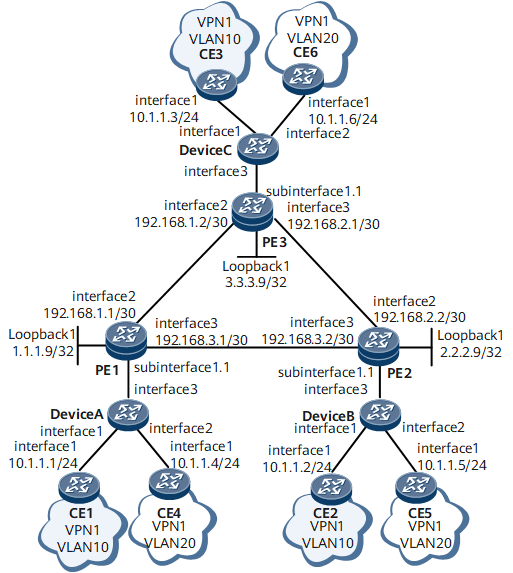
On the network shown in Figure 1, the CEs connect to the PEs through the routers, and the routers access the L3VPN through dot1q VLAN tag termination sub-interfaces. Packets sent by the routers to the PEs carry one VLAN tag. The packets sent from the routers to the PEs carry one VLAN tag. Dot1q VLAN tag termination sub-interfaces need to be configured on PE1, PE2, and PE3 and bound to a VSI or an L2VC to access the L2VPN, implementing interworking between CEs 1 through 6.
Precautions
L2VPNs include VPWS and VPLS networks.
-
VPWS is a point-to-point virtual leased line technology and supports almost all link layer protocols. VPWS simulates the traditional leased line services on IP networks and provides asymmetric and low-cost digital data network (DDN) services. For users on both ends of the leased line, VPWS is similar to the traditional leased line services.
-
VPLS makes a multipoint-to-multipoint VPN networking possible. With VPLS, the carrier can transmit Ethernet-based multipoint-to-multipoint services for users over an MPLS backbone network.
A VPLS network is used in this example to describe how to access an L2VPN using dot1q VLAN tag termination sub-interfaces so that CEs can communicate over the L2VPN. Configurations on a VPWS network are the same as those on a VPLS network except that the user-side sub-interfaces on PEs are configured as dot1q VLAN tag termination sub-interfaces and bound to an L2VC to access the L2VPN.
Configuration Roadmap
The configuration roadmap is as follows:
Configure IP addresses of interfaces on the CEs. The packets sent from the CEs to the routers do not carry any VLAN tag.
Create VLANs on the routers and determine the VLANs to which users belong.
Configure the Layer 2 forwarding function on the routers and CEs so that the packets sent from the routers to the PEs carry one VLAN tag.
Configure a VPLS network and dot1q VLAN tag termination sub-interfaces on the PEs and bind these sub-interfaces to a VSI so that users can communicate over the VPLS network.
Configure a routing protocol on the PEs so that these devices can communicate on the Layer 3 network.
Open Shortest Path First (OSPF) is used in this example.
- Configure basic Multiprotocol Label Switching (MPLS) functions and MPLS Label Distribution Protocol (LDP) on the PEs, and set up MPLS Label Switched Paths (LSPs) between these devices.
- Enable MPLS L2VPN on the PEs globally.
- Configure a VSI and dot1q VLAN tag termination sub-interfaces on the PEs, and bind these sub-interfaces to the VSI to access the L2VPN.
Data Preparation
To complete the configuration, you need the following data:
- Users' VLAN IDs and IP addresses
- Names and IP addresses of the interfaces that connect the routers and the CEs
- Names and IP addresses of the interfaces that connect the PEs and the routers
- Names and IP addresses of the interfaces that connect the PEs
- MPLS LSR IDs, VSI ID, VSI name, and name and IP address of each interface bound to the VSI on the PEs
Procedure
- Configure IP addresses of interfaces on the CEs.
# Configure CE1.
<HUAWEI> system-view
[~HUAWEI] sysname CE1
[*HUAWEI] commit
[~CE1] interface gigabitethernet 0/1/1
[*CE1-GigabitEthernet0/1/1] undo shutdown
[*CE1-GigabitEthernet0/1/1] ip address 10.1.1.1 24
[*CE1-GigabitEthernet0/1/1] quit
[*CE1] commit
# Configure CE2.
<HUAWEI> system-view
[~HUAWEI] sysname CE2
[*HUAWEI] commit
[~CE2] interface gigabitethernet 0/1/1
[*CE2-GigabitEthernet0/1/1] undo shutdown
[*CE2-GigabitEthernet0/1/1] ip address 10.1.1.2 24
[*CE2-GigabitEthernet0/1/1] quit
[*CE2] commit
# Configure CE3.
<HUAWEI> system-view
[~HUAWEI] sysname CE3
[*HUAWEI] commit
[~CE3] interface gigabitethernet 0/1/1
[*CE3-GigabitEthernet0/1/1] undo shutdown
[*CE3-GigabitEthernet0/1/1] ip address 10.1.1.3 24
[*CE3-GigabitEthernet0/1/1] quit
[*CE3] commit
# Configure CE4.
<HUAWEI> system-view
[~HUAWEI] sysname CE4
[*HUAWEI] commit
[~CE4] interface gigabitethernet 0/1/1
[*CE4-GigabitEthernet0/1/1] undo shutdown
[*CE4-GigabitEthernet0/1/1] ip address 10.1.1.4 24
[*CE4-GigabitEthernet0/1/1] quit
[*CE4] commit
# Configure CE5.
<HUAWEI> system-view
[~HUAWEI] sysname CE5
[*HUAWEI] commit
[~CE5] interface gigabitethernet 0/1/1
[*CE5-GigabitEthernet0/1/1] undo shutdown
[*CE5-GigabitEthernet0/1/1] ip address 10.1.1.5 24
[*CE5-GigabitEthernet0/1/1] quit
[*CE5] commit
# Configure CE6.
<HUAWEI> system-view
[~HUAWEI] sysname CE6
[*HUAWEI] commit
[~CE6] interface gigabitethernet 0/1/1
[*CE6-GigabitEthernet0/1/1] undo shutdown
[*CE6-GigabitEthernet0/1/1] ip address 10.1.1.6 24
[*CE6-GigabitEthernet0/1/1] quit
[*CE6] commit
- Create VLANs on the routers and associate Layer 2 interfaces with the VLANs.
# Configure Device A.
<HUAWEI> system-view
[~HUAWEI] sysname DeviceA
[*HUAWEI] commit
[~DeviceA] vlan batch 10 20
[*DeviceA] interface gigabitethernet 0/1/1
[*DeviceA-GigabitEthernet0/1/1] undo shutdown
[*DeviceA-GigabitEthernet0/1/1] portswitch
[*DeviceA-GigabitEthernet0/1/1] port link-type access
[*DeviceA-GigabitEthernet0/1/1] port default vlan 10
[*DeviceA-GigabitEthernet0/1/1] quit
[*DeviceA] interface gigabitethernet 0/1/2
[*DeviceA-GigabitEthernet0/1/2] undo shutdown
[*DeviceA-GigabitEthernet0/1/2] portswitch
[*DeviceA-GigabitEthernet0/1/2] port link-type access
[*DeviceA-GigabitEthernet0/1/2] port default vlan 20
[*DeviceA-GigabitEthernet0/1/2] quit
[*DeviceA] commit
# Configure Device B.
<HUAWEI> system-view
[~HUAWEI] sysname DeviceB
[*HUAWEI] commit
[~DeviceB] vlan batch 10 20
[*DeviceB] interface gigabitethernet 0/1/1
[*DeviceB-GigabitEthernet0/1/1] undo shutdown
[*DeviceB-GigabitEthernet0/1/1] portswitch
[*DeviceB-GigabitEthernet0/1/1] port link-type access
[*DeviceB-GigabitEthernet0/1/1] port default vlan 10
[*DeviceB-GigabitEthernet0/1/1] quit
[*DeviceB] interface gigabitethernet 0/1/2
[*DeviceB-GigabitEthernet0/1/2] undo shutdown
[*DeviceB-GigabitEthernet0/1/2] portswitch
[*DeviceB-GigabitEthernet0/1/2] port link-type access
[*DeviceB-GigabitEthernet0/1/2] port default vlan 20
[*DeviceB-GigabitEthernet0/1/2] quit
[*DeviceB] commit
# Configure Device C.
<HUAWEI> system-view
[~HUAWEI] sysname DeviceC
[*HUAWEI] commit
[~DeviceC] vlan batch 10 20
[*DeviceC] interface gigabitethernet 0/1/1
[*DeviceC-GigabitEthernet0/1/1] undo shutdown
[*DeviceC-GigabitEthernet0/1/1] portswitch
[*DeviceC-GigabitEthernet0/1/1] port link-type access
[*DeviceC-GigabitEthernet0/1/1] port default vlan 10
[*DeviceC-GigabitEthernet0/1/1] quit
[*DeviceC] interface gigabitethernet 0/1/2
[*DeviceC-GigabitEthernet0/1/2] undo shutdown
[*DeviceC-GigabitEthernet0/1/2] portswitch
[*DeviceC-GigabitEthernet0/1/2] port link-type access
[*DeviceC-GigabitEthernet0/1/2] port default vlan 20
[*DeviceC-GigabitEthernet0/1/2] quit
[*DeviceC] commit
- Configure the Layer 2 forwarding function.
# Configure Device A.
[~DeviceA] interface gigabitethernet 0/1/3
[*DeviceA-GigabitEthernet0/1/3] undo shutdown
[*DeviceA-GigabitEthernet0/1/3] portswitch
[*DeviceA-GigabitEthernet0/1/3] port link-type trunk
[*DeviceA-GigabitEthernet0/1/3] port trunk allow-pass vlan 10 20
[*DeviceA-GigabitEthernet0/1/3] quit
[*DeviceA] commit
# Configure Device B.
[~DeviceB] interface gigabitethernet 0/1/3
[*DeviceB-GigabitEthernet0/1/3] undo shutdown
[*DeviceB-GigabitEthernet0/1/3] portswitch
[*DeviceB-GigabitEthernet0/1/3] port link-type trunk
[*DeviceB-GigabitEthernet0/1/3] port trunk allow-pass vlan 10 20
[*DeviceB-GigabitEthernet0/1/3] quit
[*DeviceB] commit
# Configure Device C.
[~DeviceC] interface gigabitethernet 0/1/3
[*DeviceC-GigabitEthernet0/1/3] undo shutdown
[*DeviceC-GigabitEthernet0/1/3] portswitch
[*DeviceC-GigabitEthernet0/1/3] port link-type trunk
[*DeviceC-GigabitEthernet0/1/3] port trunk allow-pass vlan 10 20
[*DeviceC-GigabitEthernet0/1/3] quit
[*DeviceC] commit

If the interface is already a Layer 2 interface, do not run the portswitch command.
- Configure a VPLS network.
-
Assign an IP address to each interface on each PE. After OSPF is enabled, the 32-bit loopback interface address of each PE must be advertised.
# Configure PE1.
<HUAWEI> system-view
[~HUAWEI] sysname PE1
[*HUAWEI] commit
[~PE1] interface loopback 1
[*PE1-LoopBack1] ip address 1.1.1.9 32
[*PE1-LoopBack1] quit
[*PE1] interface gigabitethernet 0/1/2
[*PE1-GigabitEthernet0/1/2] ip address 192.168.1.1 24
[*PE1-GigabitEthernet0/1/2] undo shutdown
[*PE1-GigabitEthernet0/1/2] quit
[*PE1] interface gigabitethernet 0/1/3
[*PE1-GigabitEthernet0/1/3] ip address 192.168.3.1 24
[*PE1-GigabitEthernet0/1/3] undo shutdown
[*PE1-GigabitEthernet0/1/3] quit
[*PE1] ospf
[*PE1-ospf-1] area 0
[*PE1-ospf-1-area-0.0.0.0] network 1.1.1.9 0.0.0.0
[*PE1-ospf-1-area-0.0.0.0] network 192.168.1.0 0.0.0.255
[*PE1-ospf-1-area-0.0.0.0] network 192.168.3.0 0.0.0.255
[*PE1-ospf-1-area-0.0.0.0] quit
[*PE1-ospf-1] quit
[*PE1] commit
# Configure PE2.
<HUAWEI> system-view
[~HUAWEI] sysname PE2
[*HUAWEI] commit
[~PE2] interface LoopBack 1
[*PE2-LoopBack1] ip address 2.2.2.9 32
[*PE2-LoopBack1] quit
[*PE2] interface gigabitethernet 0/1/2
[*PE2-GigabitEthernet0/1/2] ip address 192.168.2.2 24
[*PE2-GigabitEthernet0/1/2] undo shutdown
[*PE2-GigabitEthernet0/1/2] quit
[*PE2] interface gigabitethernet 0/1/3
[*PE2-GigabitEthernet0/1/3] ip address 192.168.3.2 24
[*PE2-GigabitEthernet0/1/3] undo shutdown
[*PE2-GigabitEthernet0/1/3] quit
[*PE2] ospf
[*PE2-ospf-1] area 0
[*PE2-ospf-1-area-0.0.0.0] network 2.2.2.9 0.0.0.0
[*PE2-ospf-1-area-0.0.0.0] network 192.168.2.0 0.0.0.255
[*PE2-ospf-1-area-0.0.0.0] network 192.168.3.0 0.0.0.255
[*PE2-ospf-1-area-0.0.0.0] quit
[*PE2-ospf-1] quit
[*PE2] commit
# Configure PE3.
<HUAWEI> system-view
[~HUAWEI] sysname PE3
[*HUAWEI] commit
[~PE3] interface loopback 1
[*PE3-LoopBack1] ip address 3.3.3.9 32
[*PE3-LoopBack1] quit
[*PE3] interface gigabitethernet 0/1/2
[*PE3-GigabitEthernet0/1/2] ip address 192.168.1.2 24
[*PE3-GigabitEthernet0/1/2] undo shutdown
[*PE3-GigabitEthernet0/1/2] quit
[*PE3] interface gigabitethernet 0/1/3
[*PE3-GigabitEthernet0/1/3] ip address 192.168.2.1 24
[*PE3-GigabitEthernet0/1/3] undo shutdown
[*PE3-GigabitEthernet0/1/3] quit
[*PE3] ospf
[*PE3-ospf-1] area 0
[*PE3-ospf-1-area-0.0.0.0] network 3.3.3.9 0.0.0.0
[*PE3-ospf-1-area-0.0.0.0] network 192.168.1.0 0.0.0.255
[*PE3-ospf-1-area-0.0.0.0] network 192.168.2.0 0.0.0.255
[*PE3-ospf-1-area-0.0.0.0] quit
[*PE3-ospf-1] quit
[*PE3] commit
After the configurations are complete, PE1 and PE2 both have routes, discovered by OSPF, to loopback1 of each other. PE1 and PE3 also have routes, discovered by OSPF, to loopback1 of each other.
Use the command output on PE1 as an example.
[~PE1] display ip routing-table
Route Flags: R - relay, D - download to fib, T - to vpn-instance, B - black hole route ------------------------------------------------------------------------------
Routing Table : _public_
         Destinations : 14       Routes : 14

Destination/Mask    Proto  Pre  Cost        Flags NextHop         Interface

        1.1.1.9/32  Direct 0    0             D  127.0.0.1       LoopBack1
        2.2.2.9/32  OSPF   10   1             D  192.168.3.2     GigabitEthernet0/1/3
        3.3.3.9/32  OSPF   10   1             D  192.168.1.2     GigabitEthernet0/1/2
    192.168.1.0/24  Direct 0    0             D  192.168.1.1     GigabitEthernet0/1/2
    192.168.1.1/32  Direct 0    0             D  127.0.0.1       GigabitEthernet0/1/2
  192.168.1.255/32  Direct 0    0             D  127.0.0.1       GigabitEthernet0/1/2
    192.168.2.0/24  OSPF   10   2             D  192.168.3.2     GigabitEthernet0/1/3
                    OSPF   10   2             D  192.168.1.2     GigabitEthernet0/1/2
    192.168.3.0/24  Direct 0    0             D  192.168.3.1     GigabitEthernet0/1/3
    192.168.3.1/32  Direct 0    0             D  127.0.0.1       GigabitEthernet0/1/3
  192.168.3.255/32  Direct 0    0             D  127.0.0.1       GigabitEthernet0/1/3
       127.0.0.0/8  Direct 0    0             D  127.0.0.1       InLoopBack0
      127.0.0.1/32  Direct 0    0             D  127.0.0.1       InLoopBack0
127.255.255.255/32  Direct 0    0             D  127.0.0.1       InLoopBack0
255.255.255.255/32  Direct 0    0             D  127.0.0.1       InLoopBack0
[*PE1] ping 192.168.2.2
  PING 192.168.2.2: 56  data bytes, press CTRL_C to break
    Reply from 192.168.2.2: bytes=56 Sequence=1 ttl=254 time=6 ms
    Reply from 192.168.2.2: bytes=56 Sequence=2 ttl=254 time=2 ms
    Reply from 192.168.2.2: bytes=56 Sequence=3 ttl=254 time=1 ms
    Reply from 192.168.2.2: bytes=56 Sequence=4 ttl=254 time=2 ms
    Reply from 192.168.2.2: bytes=56 Sequence=5 ttl=254 time=1 ms

  --- 192.168.2.2 ping statistics ---
    5 packet(s) transmitted
    5 packet(s) received
    0.00% packet loss
    round-trip min/avg/max = 1/2/6 ms
Enable basic MPLS functions and MPLS LDP.
# Configure PE1.
[*PE1] mpls lsr-id 1.1.1.9
[*PE1] mpls
[*PE1-mpls] quit
[*PE1] mpls ldp
[*PE1-mpls-ldp] quit
[*PE1] interface gigabitethernet 0/1/2
[*PE1-GigabitEthernet0/1/2] mpls
[*PE1-GigabitEthernet0/1/2] mpls ldp
[*PE1-GigabitEthernet0/1/2] quit
[*PE1] interface gigabitethernet 0/1/3
[*PE1-GigabitEthernet0/1/3] mpls
[*PE1-GigabitEthernet0/1/3] mpls ldp
[*PE1-GigabitEthernet0/1/3] quit
[*PE1] commit
# Configure PE2.
[~PE2] mpls lsr-id 2.2.2.9
[*PE2] mpls
[*PE2-mpls] quit
[*PE2] mpls ldp
[*PE2-mpls-ldp] quit
[*PE2] interface gigabitethernet0/1/2
[*PE2-GigabitEthernet0/1/2] mpls
[*PE2-GigabitEthernet0/1/2] mpls ldp
[*PE2-GigabitEthernet0/1/2] quit
[*PE2] interface gigabitethernet0/1/3
[*PE2-GigabitEthernet0/1/3] mpls
[*PE2-GigabitEthernet0/1/3] mpls ldp
[*PE2-GigabitEthernet0/1/3] quit
[*PE2] commit
# Configure PE3.
[~PE3] mpls lsr-id 3.3.3.9
[*PE3] mpls
[*PE3-mpls] quit
[*PE3] mpls ldp
[*PE3-mpls-ldp] quit
[*PE3] interface gigabitethernet 0/1/2
[*PE3-GigabitEthernet0/1/2] mpls
[*PE3-GigabitEthernet0/1/2] mpls ldp
[*PE3-GigabitEthernet0/1/2] quit
[*PE3] interface gigabitethernet 0/1/3
[*PE3-GigabitEthernet0/1/3] mpls
[*PE3-GigabitEthernet0/1/3] mpls ldp
[*PE3-GigabitEthernet0/1/3] quit
[*PE3] commit
After the configurations are complete, LDP sessions are set up between PEs. Run the display mpls ldp session command. The command output shows that the LDP session status is Operational.
Use the command output on PE1 as an example.
[~PE1] display mpls ldp session
 LDP Session(s) in Public Network

 Codes: LAM(Label Advertisement Mode), SsnAge Unit(DDDD:HH:MM)
 An asterisk (*) before a session means the session is being deleted.
--------------------------------------------------------------------------
 PeerID             Status       LAM  SsnRole  SsnAge       KASent/Rcv
--------------------------------------------------------------------------
 2.2.2.9:0          Operational  DU   Passive  0000:00:01   6/6
 3.3.3.9:0          Operational  DU   Passive  0000:00:00   1/1
--------------------------------------------------------------------------
TOTAL: 2 Session(s) Found.
If PEs are not directly connected, run the mpls ldp remote-peer command and remote-ip command to set up a remote LDP session between PEs.
-
# Configure PE1.
[*PE1] mpls l2vpn
[*PE1-l2vpn] quit
[*PE1] commit
# Configure PE2.
[~PE2] mpls l2vpn
[*PE2-l2vpn] quit
[*PE2] commit
# Configure PE3.
[~PE3] mpls l2vpn
[*PE3-l2vpn] quit
[*PE3] commit
Configure a VSI and bind the dot1q VLAN tag termination sub-interfaces to the VSI.
# Configure PE1.
[~PE1] vsi ldp1 static
[*PE1-vsi-ldp1] pwsignal ldp
[*PE1-vsi-ldp1-ldp] vsi-id 2
[*PE1-vsi-ldp1-ldp] peer 2.2.2.9
[*PE1-vsi-ldp1-ldp] peer 3.3.3.9
[*PE1-vsi-ldp1-ldp] quit
[*PE1-vsi-ldp1] quit
[*PE1] interface gigabitethernet 0/1/1.1
[*PE1-GigabitEthernet0/1/1.1] control-vid 1 dot1q-termination
[*PE1-GigabitEthernet0/1/1.1] dot1q termination vid 10
[*PE1-GigabitEthernet0/1/1.1] dot1q termination vid 20
[*PE1-GigabitEthernet0/1/1.1] l2 binding vsi ldp1
[*PE1-GigabitEthernet0/1/1.1] quit
[*PE1] commit
# Configure PE2.
[~PE2] vsi ldp1 static
[*PE2-vsi-ldp1] pwsignal ldp
[*PE2-vsi-ldp1-ldp] vsi-id 2
[*PE2-vsi-ldp1-ldp] peer 1.1.1.9
[*PE2-vsi-ldp1-ldp] peer 3.3.3.9
[*PE2-vsi-ldp1-ldp] quit
[*PE2-vsi-ldp1] quit
[*PE2] interface gigabitethernet 0/1/1.1
[*PE2-GigabitEthernet0/1/1.1] control-vid 1 dot1q-termination
[*PE2-GigabitEthernet0/1/1.1] dot1q termination vid 10
[*PE2-GigabitEthernet0/1/1.1] dot1q termination vid 20
[*PE2-GigabitEthernet0/1/1.1] l2 binding vsi ldp1
[*PE2-GigabitEthernet0/1/1.1] quit
[*PE2] commit
# Configure PE3.
[~PE3] vsi ldp1 static
[*PE3-vsi-ldp1] pwsignal ldp
[*PE3-vsi-ldp1-ldp] vsi-id 2
[*PE3-vsi-ldp1-ldp] peer 1.1.1.9
[*PE3-vsi-ldp1-ldp] peer 2.2.2.9
[*PE3-vsi-ldp1-ldp] quit
[*PE3-vsi-ldp1] quit
[*PE3] interface gigabitethernet 0/1/1.1
[*PE3-GigabitEthernet0/1/1.1] control-vid 1 dot1q-termination
[*PE3-GigabitEthernet0/1/1.1] dot1q termination vid 10
[*PE3-GigabitEthernet0/1/1.1] dot1q termination vid 20
[*PE3-GigabitEthernet0/1/1.1] l2 binding vsi ldp1
[*PE3-GigabitEthernet0/1/1.1] quit
[*PE3] commit
When you run the dot1q termination command on an interface, make sure that the VLAN tag values of the two different sub-interfaces are different.
After the configurations are complete, run the display vsi name ldp1 verbose command on PE1. The command output shows that PWs to PE2 and PE3 are set up on the VSI named ldp1 and that the VSI status is up.[~PE1] display vsi name ldp1 verbose ***VSI Name : ldp1 Administrator VSI : no Isolate Spoken : disable VSI Index : 1 PW Signaling : ldp Member Discovery Style : static Bridge-domain Mode : disable PW MAC Learn Style : unqualify Encapsulation Type : vlan MTU : 1500 Diffserv Mode : uniform Service Class : -- Color : -- DomainId : 255 Domain Name : Ignore AcState : disable P2P VSI : disable Create Time : 0 days, 0 hours, 3 minutes, 8 seconds VSI State : up VSI ID : 2 *Peer Router ID : 2.2.2.9 primary or secondary : primary ignore-standby-state : no VC Label : 17 Peer Type : dynamic Session : up Tunnel ID :0x0000000001006a5c21 Broadcast Tunnel ID : -- Broad BackupTunnel ID : -- CKey : 1 NKey : 3154116711 Stp Enable : 0 PwIndex : 0 Control Word : disable *Peer Router ID : 3.3.3.9 primary or secondary : primary ignore-standby-state : no VC Label : 18 Peer Type : dynamic Session : up Tunnel ID : 0x0000000001004c4b43 Broadcast Tunnel ID : -- Broad BackupTunnel ID : -- CKey : 2 NKey : 3154116712 Stp Enable : 0 PwIndex : 0 Control Word : disable Interface Name : GigabitEthernet0/1/1.1 State : up Access Port : false Last Up Time : 2012/07/19 03:19:14 Total Up Time : 0 days, 0 hours, 3 minutes, 11 seconds **PW Information: *Peer Ip Address : 2.2.2.9 PW State : up Local VC Label : 17 Remote VC Label : 17 Remote Control Word : disable PW Type : label Tunnel ID : 0x0000000001006a5c21 Broadcast Tunnel ID : -- Broad BackupTunnel ID : -- Ckey : 1 Nkey : 3154116711 Main PW Token : 0x0 Slave PW Token : 0x0 Tnl Type : ldp OutInterface : LDP LSP Backup OutInterface : Stp Enable : 0 PW Last Up Time : 2012/07/19 03:21:09 PW Total Up Time : 0 days, 0 hours, 0 minutes, 29 seconds *Peer Ip Address : 3.3.3.9 PW State : up Local VC Label : 18 Remote VC Label : 17 Remote Control Word : disable PW Type : label Tunnel ID : 0x0000000001004c4b43 Broadcast Tunnel ID : -- Broad BackupTunnel ID : -- Ckey : 2 Nkey : 3154116712 Main PW Token : 0x0 Slave PW Token : 0x0 Tnl Type : ldp OutInterface : LDP LSP Backup OutInterface : Stp Enable : 0 PW Last Up Time : 2012/07/19 03:21:09 PW Total Up Time : 0 days, 0 hours, 0 minutes, 29 seconds
-
- Verify the configuration.
After the configurations are complete, run the display dot1q information termination interface command to view information about the dot1q VLAN tag termination sub-interfaces. The command output shows that the sub-interfaces are bound to the VSI.
Use the command output on PE1 as an example.
[*PE1] display dot1q information termination interface gigabitethernet 0/1/1
  GigabitEthernet0/1/1.1
    VSI bound
    Total QinQ Num: 2
      dot1q  termination vid 10
      dot1q  termination vid 20
    Total vlan-group Num: 0
    encapsulation dot1q-termination
Hosts attached to CE1, CE2, and CE3 can ping each other.
[~CE1] ping 10.1.1.2
  PING 10.1.1.2: 56  data bytes, press CTRL_C to break
    Reply from 10.1.1.2: bytes=56 Sequence=1 ttl=255 time=43 ms
    Reply from 10.1.1.2: bytes=56 Sequence=2 ttl=255 time=33 ms
    Reply from 10.1.1.2: bytes=56 Sequence=3 ttl=255 time=98 ms
    Reply from 10.1.1.2: bytes=56 Sequence=4 ttl=255 time=181 ms
    Reply from 10.1.1.2: bytes=56 Sequence=5 ttl=255 time=129 ms

  --- 10.1.1.2 ping statistics ---
    5 packet(s) transmitted
    5 packet(s) received
    0.00% packet loss
    round-trip min/avg/max = 33/96/181 ms
[~CE1] ping 10.1.1.3
  PING 10.1.1.3: 56  data bytes, press CTRL_C to break
    Reply from 10.1.1.3: bytes=56 Sequence=1 ttl=255 time=3 ms
    Reply from 10.1.1.3: bytes=56 Sequence=2 ttl=255 time=2 ms
    Reply from 10.1.1.3: bytes=56 Sequence=3 ttl=255 time=2 ms
    Reply from 10.1.1.3: bytes=56 Sequence=4 ttl=255 time=2 ms
    Reply from 10.1.1.3: bytes=56 Sequence=5 ttl=255 time=2 ms

  --- 10.1.1.3 ping statistics ---
    5 packet(s) transmitted
    5 packet(s) received
    0.00% packet loss
    round-trip min/avg/max = 2/2/3 ms
Configuration Files
PE1 configuration file
#
 sysname PE1
#
 mpls lsr-id 1.1.1.9
#
 mpls
#
 mpls l2vpn
#
vsi ldp1 static
 pwsignal ldp
  vsi-id 2
  peer 3.3.3.9
  peer 2.2.2.9
#
mpls ldp
#
interface GigabitEthernet0/1/1
 undo shutdown
#
interface GigabitEthernet0/1/1.1
 encapsulation dot1q-termination
 dot1q termination vid 10
 dot1q termination vid 20
 l2 binding vsi ldp1
#
interface GigabitEthernet0/1/2
 undo shutdown
 ip address 192.168.1.1 255.255.255.252
 mpls
 mpls ldp
#
interface GigabitEthernet0/1/3
 undo shutdown
 ip address 192.168.3.1 255.255.255.252
 mpls
 mpls ldp
#
interface LoopBack1
 ip address 1.1.1.9 255.255.255.255
#
ospf 1
 area 0.0.0.0
  network 1.1.1.9 0.0.0.0
  network 192.168.1.0 0.0.0.3
  network 192.168.3.0 0.0.0.3
#
return
PE2 configuration file
#
 sysname PE2
#
 mpls lsr-id 2.2.2.9
#
 mpls
#
 mpls l2vpn
#
vsi ldp1 static
 pwsignal ldp
  vsi-id 2
  peer 1.1.1.9
  peer 3.3.3.9
#
mpls ldp
#
interface GigabitEthernet0/1/1
 undo shutdown
#
interface GigabitEthernet0/1/1.1
 encapsulation dot1q-termination
 dot1q termination vid 10
 dot1q termination vid 20
 l2 binding vsi ldp1
#
interface GigabitEthernet0/1/2
 undo shutdown
 ip address 192.168.2.2 255.255.255.252
 mpls
 mpls ldp
#
interface GigabitEthernet0/1/3
 undo shutdown
 ip address 192.168.3.2 255.255.255.252
 mpls
 mpls ldp
#
interface LoopBack1
 ip address 2.2.2.9 255.255.255.255
#
ospf 1
 area 0.0.0.0
  network 2.2.2.9 0.0.0.0
  network 192.168.3.0 0.0.0.3
  network 192.168.2.0 0.0.0.3
#
return
PE3 configuration file
#
 sysname PE3
#
 mpls lsr-id 3.3.3.9
#
 mpls
#
 mpls l2vpn
#
vsi ldp1 static
 pwsignal ldp
  vsi-id 2
  peer 1.1.1.9
  peer 2.2.2.9
#
mpls ldp
#
interface GigabitEthernet0/1/1
 undo shutdown
#
interface GigabitEthernet0/1/1.1
 encapsulation dot1q-termination
 dot1q termination vid 10
 dot1q termination vid 20
 l2 binding vsi ldp1
#
interface GigabitEthernet0/1/2
 undo shutdown
 ip address 192.168.1.2 255.255.255.252
 mpls
 mpls ldp
#
interface GigabitEthernet0/1/3
 undo shutdown
 ip address 192.168.2.1 255.255.255.252
 mpls
 mpls ldp
#
interface LoopBack1
 ip address 3.3.3.9 255.255.255.255
#
ospf 1
 area 0.0.0.0
  network 3.3.3.9 0.0.0.0
  network 192.168.1.0 0.0.0.3
  network 192.168.2.0 0.0.0.3
#
return
Device A configuration file
#
 sysname DeviceA
#
 vlan batch 10 20
#
interface GigabitEthernet0/1/1
 portswitch
 undo shutdown
 port link-type access
 port default vlan 10
#
interface GigabitEthernet0/1/2
 portswitch
 undo shutdown
 port link-type access
 port default vlan 20
#
interface GigabitEthernet0/1/3
 portswitch
 undo shutdown
 port link-type trunk
 port trunk allow-pass vlan 10 20
#
return
Device B configuration file
#
 sysname DeviceB
#
 vlan batch 10 20
#
interface GigabitEthernet0/1/1
 portswitch
 undo shutdown
 port link-type access
 port default vlan 10
#
interface GigabitEthernet0/1/2
 portswitch
 undo shutdown
 port link-type access
 port default vlan 20
#
interface GigabitEthernet0/1/3
 portswitch
 undo shutdown
 port link-type trunk
 port trunk allow-pass vlan 10 20
#
return
Device C configuration file
#
 sysname DeviceC
#
 vlan batch 10 20
#
interface GigabitEthernet0/1/1
 portswitch
 undo shutdown
 port link-type access
 port default vlan 10
#
interface GigabitEthernet0/1/2
 portswitch
 undo shutdown
 port link-type access
 port default vlan 20
#
interface GigabitEthernet0/1/3
 portswitch
 undo shutdown
 port link-type trunk
 port trunk allow-pass vlan 10 20
#
return
CE1 configuration file
#
 sysname CE1
#
interface GigabitEthernet0/1/1
 undo shutdown
 ip address 10.1.1.1 255.255.255.0
#
return
CE2 configuration file
#
 sysname CE2
#
interface GigabitEthernet0/1/1
 undo shutdown
 ip address 10.1.1.2 255.255.255.0
#
return
CE3 configuration file
#
 sysname CE3
#
interface GigabitEthernet0/1/1
 undo shutdown
 ip address 10.1.1.3 255.255.255.0
#
return
CE4 configuration file
#
 sysname CE4
#
interface GigabitEthernet0/1/1
 undo shutdown
 ip address 10.1.1.4 255.255.255.0
#
return
CE5 configuration file
#
 sysname CE5
#
interface GigabitEthernet0/1/1
 undo shutdown
 ip address 10.1.1.5 255.255.255.0
#
return
CE6 configuration file
#
 sysname CE6
#
interface GigabitEthernet0/1/1
 undo shutdown
 ip address 10.1.1.6 255.255.255.0
#
return