Example for Configuring a QinQ VLAN Tag Termination Sub-Interface to Support the Local Connection
This example shows how to configure the QinQ VLAN tag termination sub-interface to support the local connection. This configuration enables CEs to communicate with each other after being connected to the same virtual switching instance (VSI) on a PE through the sub-interface.
Networking Requirements
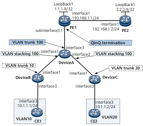
On the network shown in Figure 1, CE1 and CE2 are connected to PE1 through routers and access the virtual private LAN service (VPLS) network through PE1. The packets sent from Device A to PE1 carry two VLAN tags and the outer VLAN tags are the same. Because the packets received by the user-side interface of PE1 have the same outer VLAN tag, this user-side interface does not forward these packets. As a result, users from different VLANs cannot communicate in the same VSI. QinQ VLAN tag termination sub-interfaces need to be configured to support the local connection on the PEs, ensuring communication between the CEs.
Precautions
If the packets received by the user-side interface of PE1 are forwarded through this interface, GE 0/1/3 and GE 0/1/1 on Device A will learn the same MAC address and therefore cannot forward packets correctly. Therefore, MAC address learning must be disabled on Device A that is connected to the user-side interface of PE1.
Configuration Roadmap
The configuration roadmap is as follows:
Configure IP addresses of interfaces on the CEs. The packets sent from the CEs to the routers do not carry any VLAN tag.
Create VLANs and configure the Layer 2 forwarding function on Device B and Device C so that the packets sent from Device B and Device C to Device A carry one VLAN tag.
Configure the QinQ and Layer 2 forwarding functions on Device A so that the packets sent from Device A to PE1 carry two VLAN tags.
Enable communication between different users in a VSI.
Configure a routing protocol on the PEs so that these devices can communicate on the Layer 3 network.
Open Shortest Path First (OSPF) is used in this example.
- Configure basic Multiprotocol Label Switching (MPLS) functions and MPLS Label Distribution Protocol (LDP) on the PEs, and set up MPLS Label Switched Paths (LSPs) between these devices.
- Enable MPLS L2VPN on the PEs globally.
- Configure QinQ VLAN tag termination sub-interfaces on the PEs, bind the sub-interfaces to a VSI to access the VPLS network, and configure the sub-interface on PE1 to support the local connection.
Users can communicate in a VSI.
- Disable MAC address learning on Device A to prevent two interfaces of Device A from learning the same MAC address.
Data Preparation
To complete the configuration, you need the following data:
- Users' VLAN IDs and IP addresses
- Outer VLAN tag in the packets sent from Device A to PE1
Names of the interfaces that connect the routers and the CEs
Names of the interfaces that connect the routers
Names of the interfaces that connect router A and PE1
- MPLS LSR IDs, VSI ID, VSI name, and name and IP address of each interface bound to the VSI on the PEs
Procedure
- Configure IP addresses of interfaces on the CEs.
# Configure CE1.
<HUAWEI> system-view
[~HUAWEI] sysname CE1
[*HUAWEI] commit
[~CE1] interface gigabitethernet 0/1/3
[*CE1-GigabitEthernet0/1/3] undo shutdown
[*CE1-GigabitEthernet0/1/3] ip address 10.1.1.1 24
[*CE1] commit
# Configure CE2.
<HUAWEI> system-view
[~HUAWEI] sysname CE2
[*HUAWEI] commit
[~CE2] interface gigabitethernet 0/1/3
[*CE2-GigabitEthernet0/1/3] undo shutdown
[*CE2-GigabitEthernet0/1/3] ip address 10.1.1.2 24
[*CE2] commit
- Create VLANs and configure the Layer 2 forwarding function on Device B and Device C.
# Configure Device B.
<HUAWEI> system-view
[~HUAWEI] sysname DeviceB
[*HUAWEI] commit
[~DeviceB] vlan 10
[*DeviceB-vlan10] quit
[*DeviceB] interface gigabitethernet 0/1/3
[*DeviceB-GigabitEthernet0/1/3] undo shutdown
[*DeviceB-GigabitEthernet0/1/3] portswitch
[*DeviceB-GigabitEthernet0/1/3] port link-type access
[*DeviceB-GigabitEthernet0/1/3] port default vlan 10
[*DeviceB-GigabitEthernet0/1/3] quit
[*DeviceB] interface gigabitethernet 0/1/1
[*DeviceB-GigabitEthernet0/1/1] undo shutdown
[*DeviceB-GigabitEthernet0/1/1] portswitch
[*DeviceB-GigabitEthernet0/1/1] port link-type trunk
[*DeviceB-GigabitEthernet0/1/1] port trunk allow-pass vlan 10
[*DeviceB-GigabitEthernet0/1/1] quit
[*DeviceB] commit
# Configure Device C.
<HUAWEI> system-view
[~HUAWEI] sysname DeviceC
[*HUAWEI] commit
[~DeviceC] vlan 20
[*DeviceC-vlan20] quit
[*DeviceC] interface gigabitethernet 0/1/3
[*DeviceC-GigabitEthernet0/1/3] undo shutdown
[*DeviceC-GigabitEthernet0/1/3] portswitch
[*DeviceC-GigabitEthernet0/1/3] port link-type access
[*DeviceC-GigabitEthernet0/1/3] port default vlan 20
[*DeviceC-GigabitEthernet0/1/3] quit
[*DeviceC] interface gigabitethernet 0/1/1
[*DeviceC-GigabitEthernet0/1/1] undo shutdown
[*DeviceC-GigabitEthernet0/1/1] portswitch
[*DeviceC-GigabitEthernet0/1/1] port link-type trunk
[*DeviceC-GigabitEthernet0/1/1] port trunk allow-pass vlan 20
[*DeviceC-GigabitEthernet0/1/1] quit
[*DeviceC] commit
- Configure the QinQ and Layer 2 forwarding functions on Device A.
# Configure Device A.
<HUAWEI> system-view
[~HUAWEI] sysname DeviceA
[*HUAWEI] commit
[~DeviceA] vlan 100
[*DeviceA-vlan100] quit
[*DeviceA] interface gigabitethernet 0/1/1
[*DeviceA-GigabitEthernet0/1/1] undo shutdown
[*DeviceA-GigabitEthernet0/1/1] portswitch
[*DeviceA-GigabitEthernet0/1/1] port vlan-stacking vlan 10 stack-vlan 100
[*DeviceA-GigabitEthernet0/1/1] quit
[*DeviceA] interface gigabitethernet 0/1/2
[*DeviceA-GigabitEthernet0/1/2] undo shutdown
[*DeviceA-GigabitEthernet0/1/2] portswitch
[*DeviceA-GigabitEthernet0/1/2] port vlan-stacking vlan 20 stack-vlan 100
[*DeviceA-GigabitEthernet0/1/2] quit
[*DeviceA] interface gigabitethernet 0/1/3
[*DeviceA-GigabitEthernet0/1/3] undo shutdown
[*DeviceA-GigabitEthernet0/1/3] portswitch
[*DeviceA-GigabitEthernet0/1/3] port link-type trunk
[*DeviceA-GigabitEthernet0/1/3] port trunk allow-pass vlan 100
[*DeviceA-GigabitEthernet0/1/3] quit
[*DeviceA] commit

If the device does not support the port vlan-stacking command, you can run the port link-type dot1q-tunnel command and port default vlan command on the interface to configure the QinQ function.
- Configure a VPLS network.
Configure OSPF on the PEs.
Assign an IP address to each interface on each PE. After OSPF is enabled, the 32-bit loopback interface address of each PE must be advertised.
# Configure PE1.
<HUAWEI> system-view
[~HUAWEI] sysname PE1
[*HUAWEI] commit
[~PE1] interface loopback 1
[*PE1-LoopBack1] ip address 1.1.1.9 32
[*PE1-LoopBack1] quit
[*PE1] interface gigabitethernet 0/1/1
[*PE1-GigabitEthernet0/1/1] ip address 192.168.1.1 24
[*PE1-GigabitEthernet0/1/1] undo shutdown
[*PE1-GigabitEthernet0/1/1] quit
[*PE1] ospf
[*PE1-ospf-1] area 0
[*PE1-ospf-1-area-0.0.0.0] network 1.1.1.9 0.0.0.0
[*PE1-ospf-1-area-0.0.0.0] network 192.168.1.0 0.0.0.255
[*PE1-ospf-1-area-0.0.0.0] quit
[*PE1-ospf-1] quit
[*PE1] commit
# Configure PE2.
<HUAWEI> system-view
[~HUAWEI] sysname PE2
[*HUAWEI] commit
[~PE2] interface LoopBack 1
[*PE2-LoopBack1] ip address 2.2.2.9 32
[*PE2-LoopBack1] quit
[*PE2] interface gigabitethernet 0/1/1
[*PE2-GigabitEthernet0/1/1] ip address 192.168.1.2 24
[*PE2-GigabitEthernet0/1/1] undo shutdown
[*PE2-GigabitEthernet0/1/1] quit
[*PE2] ospf
[*PE2-ospf-1] area 0
[*PE2-ospf-1-area-0.0.0.0] network 2.2.2.9 0.0.0.0
[*PE2-ospf-1-area-0.0.0.0] network 192.168.1.0 0.0.0.255
[*PE2-ospf-1-area-0.0.0.0] quit
[*PE2-ospf-1] quit
[*PE2] commit
After the configurations are complete, PE1 and PE2 both have routes, discovered by OSPF, to loopback1 of each other.
Use the command output on PE1 as an example.
[~PE1] display ip routing-table
Route Flags: R - relay, D - download to fib, T - to vpn-instance, B - black hole route
------------------------------------------------------------------------------
Routing Table : _public_
         Destinations : 6       Routes : 7
Destination/Mask    Proto  Pre  Cost     Flags NextHop         Interface

      1.1.1.9/32    Direct 0    0           D  127.0.0.1       LoopBack1
      2.2.2.9/32    OSPF   10   2           D  192.168.3.2     GigabitEthernet0/1/1
  192.168.1.0/30    Direct 0    0           D  192.168.1.1     GigabitEthernet0/1/1
  192.168.1.1/32    Direct 0    0           D  127.0.0.1       GigabitEthernet0/1/1
  192.168.1.2/32    Direct 0    0           D  192.168.1.2     GigabitEthernet0/1/1
     127.0.0.0/8    Direct 0    0           D  127.0.0.1       InLoopBack0
    127.0.0.1/32    Direct 0    0           D  127.0.0.1       InLoopBack0
Enable basic MPLS capabilities and MPLS LDP.
# Configure PE1.
[*PE1] mpls lsr-id 1.1.1.9
[*PE1] mpls
[*PE1-mpls] quit
[*PE1] mpls ldp
[*PE1-mpls-ldp] quit
[*PE1] interface gigabitethernet 0/1/1
[*PE1-GigabitEthernet0/1/1] mpls
[*PE1-GigabitEthernet0/1/1] mpls ldp
[*PE1-GigabitEthernet0/1/1] quit
[*PE1] commit
# Configure PE2.
[~PE2] mpls lsr-id 2.2.2.9
[*PE2] mpls
[*PE2-mpls] quit
[*PE2] mpls ldp
[*PE2-mpls-ldp] quit
[*PE2] interface gigabitethernet0/1/1
[*PE2-GigabitEthernet0/1/1] mpls
[*PE2-GigabitEthernet0/1/1] mpls ldp
[*PE2-GigabitEthernet0/1/1] quit
[*PE2] commit
After the configurations are complete, LDP sessions are set up between PEs, run the display mpls ldp session command. The command output shows that the LDP session status is Operational.
Use the command output on PE1 as an example.
[~PE1] display mpls ldp session
LDP Session(s) in Public Network
 Codes: LAM(Label Advertisement Mode), SsnAge Unit(DDDD:HH:MM)
 An asterisk (*) before a session means the session is being deleted.
 ------------------------------------------------------------------------------
 PeerID             Status      LAM  SsnRole  SsnAge      KASent/Rcv
 ------------------------------------------------------------------------------
 2.2.2.9:0          Operational DU   Passive  0000:00:09  37/37
 ------------------------------------------------------------------------------
 TOTAL: 1 session(s) Found.
If PEs are not directly connected, run the mpls ldp remote-peer command and remote-ip command to set up a remote LDP session between PEs.
Enable MPLS L2VPN.
# Configure PE1.
[*PE1] mpls l2vpn
[*PE1-l2vpn] quit
[*PE1] commit
# Configure PE2.
[~PE2] mpls l2vpn
[*PE2-l2vpn] quit
[*PE2] commit
Bind the QinQ VLAN tag termination sub-interface to a VSI, and configure the sub-interface to support the local connection.
# Configure PE1.
[~PE1] vsi ldp1 static
[*PE1-vsi-ldp1] pwsignal ldp
[*PE1-vsi-ldp1-ldp] vsi-id 1
[*PE1-vsi-ldp1-ldp] peer 2.2.2.9
[*PE1-vsi-ldp1-ldp] quit
[*PE1-vsi-ldp1] quit
[*PE1] interface gigabitethernet 0/1/3.1
[*PE1-GigabitEthernet0/1/3.1] control-vid 1 qinq-termination local-switch
[*PE1-GigabitEthernet0/1/3.1] qinq termination pe-vid 100 ce-vid 10
[*PE1-GigabitEthernet0/1/3.1] qinq termination pe-vid 100 ce-vid 20
[*PE1-GigabitEthernet0/1/3.1] l2 binding vsi ldp1
[*PE1-GigabitEthernet0/1/3.1] quit
[*PE1] commit
# Configure PE2 in the same way as PE1.
When you run the qinq termination command on an interface, if the pe-vid values of the two different sub-interfaces are the same, make sure that the ce-vid values are different.
After the configuration is complete, run the display vsi command on PE1 and PE2. The command outputs show that the VSI status is up. Use the command output on PE1 as an example.
[~PE1] display vsi
Total VSI number is 1, 1 is up, 0 is down, 1 is LDP mode, 0 is BGP mode

Vsi                             Mem    PW   Mac       Encap     Mtu   Vsi
Name                            Disc   Type Learn     Type      Value State
--------------------------------------------------------------------------
ldp1                            static ldp  unqualify vlan      1500  up
- Disable MAC address learning on Device A.
[~DeviceA] interface gigabitethernet 0/1/3
[*DeviceA-GigabitEthernet0/1/3] mac-address learning disable
[*DeviceA-GigabitEthernet0/1/3] quit
[*DeviceA] undo mac-address
[*DeviceA] commit
- Verify the configuration.
After the configurations are complete, CE1 and CE2 can ping each other.
Use CE1 as an example.
[~CE1] ping 10.1.1.2
  PING 10.1.1.2: 56  data bytes, press CTRL_C to break
    Reply from 10.1.1.2: bytes=56 Sequence=1 ttl=255 time = 2 ms
    Reply from 10.1.1.2: bytes=56 Sequence=2 ttl=255 time = 2 ms
    Reply from 10.1.1.2: bytes=56 Sequence=3 ttl=255 time = 2 ms
    Reply from 10.1.1.2: bytes=56 Sequence=4 ttl=255 time = 2 ms
    Reply from 10.1.1.2: bytes=56 Sequence=5 ttl=255 time = 2 ms

  --- 10.1.1.2 ping statistics ---
    5 packet(s) transmitted
    5 packet(s) received
    0.00% packet loss
    round-trip min/avg/max = 2/2/2 ms
Run the display mac-address command to check the MAC address entries on PE1. The command output shows that PE1 has learned the MAC addresses of GE 0/1/3 of CE1 and CE2 and the VLAN IDs in the outer and inner VLAN tags. In addition, the VLAN IDs in the outer VLAN tags are the same.
[*PE1] display mac-address dynamic
MAC address table of slot 1:
-------------------------------------------------------------------------------
MAC Address    VLAN/BD/       PEVLAN CEVLAN Port            Type      LSP/LSR-ID
               VSI/SI/EVPN                                             MAC-Tunnel
-------------------------------------------------------------------------------
00e0-fc12-3457 v1             100    20     GE0/1/3         dynamic   4/65546
00e0-fc12-3456 v1             100    10     GE0/1/3         dynamic   4/65556
-------------------------------------------------------------------------------
Total matching items on slot 1 displayed = 2
Run the display arp interface command on the CEs, and you can find that the ARP entries of the CEs are correct.
Use the command output on CE1 as an example.
[*CE1] display arp interface gigabitethernet 0/1/3
ARP timeout:1200s
IP ADDRESS      MAC ADDRESS  EXPIRE(M) TYPE INTERFACE      VPN-INSTANCE
                                       VLAN PVC
------------------------------------------------------------------------------
10.1.1.1        00e0-fc12-3456         I    GigabitEthernet0/1/3
10.1.1.2        00e0-fc12-3457  14     D    GigabitEthernet0/1/3
------------------------------------------------------------------------------
Total:2         Dynamic:1       Static:0    Interface:1    Remote:0
Configuration Files
PE1 configuration file
#
 sysname PE1
#
 mpls lsr-id 1.1.1.9
 mpls
#
 mpls l2vpn
#
vsi ldp1 static
 pwsignal ldp
  vsi-id 1
  peer 2.2.2.9
#
mpls ldp
#
interface GigabitEthernet0/1/3
 undo shutdown
#
interface GigabitEthernet0/1/3.1
 encapsulation qinq-termination local-switch
 qinq termination pe-vid 100 ce-vid 10
 qinq termination pe-vid 100 ce-vid 20
 l2 binding vsi ldp1
#
interface GigabitEthernet0/1/1
 undo shutdown
 ip address 192.168.1.1 255.255.255.252
 mpls
 mpls ldp
#
interface LoopBack1
 ip address 1.1.1.9 255.255.255.255
#
ospf 1
 area 0.0.0.0
  network 1.1.1.9 0.0.0.0
  network 192.168.1.0 0.0.0.3
#
return
Device A configuration file
#
 sysname DeviceA
#
 vlan batch 100
#
interface GigabitEthernet0/1/3
 portswitch
 undo shutdown
 port link-type trunk
 port trunk allow-pass vlan 100
#
interface GigabitEthernet0/1/1
 portswitch
 undo shutdown
 port vlan-stacking vlan 10 stack-vlan 100
#
interface GigabitEthernet0/1/2
 portswitch
 undo shutdown
 port vlan-stacking vlan 20 stack-vlan 100
#
return
Device B configuration file
#
 sysname DeviceB
#
 vlan batch 10
#
interface GigabitEthernet0/1/3
 portswitch
 undo shutdown
 port link-type access
 port default vlan 10
#
interface GigabitEthernet0/1/1
 portswitch
 undo shutdown
 port link-type trunk
 port trunk allow-pass vlan 10
#
return
Device C configuration file
#
 sysname DeviceC
#
 vlan batch 20
#
interface GigabitEthernet0/1/3
 portswitch
 undo shutdown
 port link-type access
 port default vlan 20
#
interface GigabitEthernet0/1/1
 portswitch
 undo shutdown
 port link-type trunk
 port trunk allow-pass vlan 20
#
return
CE1 configuration file
#
 sysname CE1
#
interface GigabitEthernet0/1/3
 undo shutdown
 ip address 10.1.1.1 255.255.255.0
#
return
CE2 configuration file
#
 sysname CE2
#
interface GigabitEthernet0/1/3
 undo shutdown
 ip address 10.1.1.2 255.255.255.0
#
return