Example for Configuring a QinQ VLAN Tag Termination Sub-Interface to Support DHCP Relay
This example shows how to configure the QinQ VLAN tag termination sub-interface to support Dynamic Host Configuration Protocol (DHCP) relay so that the DHCP relay agent transmits DHCP request packets from DHCP clients to a DHCP server. This configuration enables the clients to dynamically obtain IP addresses from the DHCP server.
Networking Requirements
If the DHCP client and DHCP server belong to different sub-nets, you need to deploy a DHCP relay agent to forward DHCP request packets from the client to the server so that the client can dynamically obtain IP addresses from the DHCP server.
If a DHCP client connects to a DHCP relay agent through a VLAN tag termination sub-interface, you need to configure the sub-interface to support DHCP relay on the DHCP relay agent. Without the configuration, the DHCP relay agent considers the received user packets with VLAN tags to be invalid. As a result, the DHCP client cannot dynamically obtain IP addresses from a DHCP server.
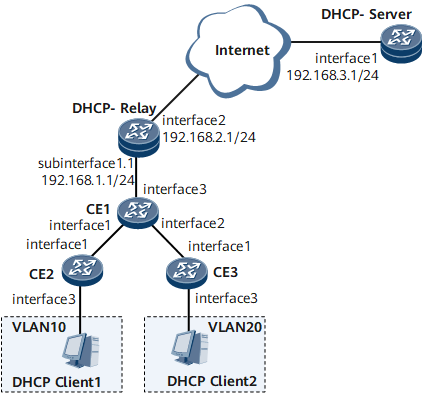
On the network shown in Figure 1, DHCP clients and a DHCP server belong to different network segments. The DHCP clients are connected to a DHCP relay agent through CE and then connected to the DHCP server through the DHCP relay agent. The packets sent from CE1 to the DHCP relay agent carry two VLAN tags. On the DHCP relay agent, the QinQ VLAN tag termination sub-interface needs to be configured to support DHCP relay, ensuring that DHCP clients can dynamically obtain IP addresses from the DHCP server.
Precautions
If the DHCP client sends broadcast packets, the interface that has DHCP relay enabled must support broadcast.
Configuration Roadmap
The configuration roadmap is as follows:
Create VLANs and configure the Layer 2 forwarding function on CE2 and CE3 so that the packets sent from CE2 and CE3 to CE1 carry one VLAN tag.
Configure the QinQ and Layer 2 forwarding functions on CE1 so that the packets sent from CE1 to the DHCP relay agent carry two VLAN tags.
Configure DHCP relay on the DHCP relay agent and configure the QinQ VLAN tag termination sub-interface to support DHCP relay so that the DHCP clients and server can communicate using DHCP packets.
Enable basic DHCP functions and configure an address pool on the DHCP server so that the DHCP server can assign IP addresses correctly.
Data Preparation
To complete the configuration, you need the following data:
- User VLAN IDs
- Names of the interfaces that connect CE (CE2 and CE3) and DHCP clients
- Names of interfaces that connect CE
- Names and IP addresses of the interfaces that connect the DHCP relay agent and CE1
- Names and IP addresses of the interfaces that connect the DHCP relay agent and the DHCP server
- Outer VLAN tag in packets to be terminated by the QinQ VLAN tag termination sub-interfaces
- IP address pool range of the DHCP server
Procedure
- Create VLANs and configure the Layer 2 forwarding function on CE2 and CE3.
# Configure CE2.
<HUAWEI> system-view
[~HUAWEI] sysname CE2
[*HUAWEI] commit
[~CE2] vlan 10
[*CE2-vlan10] quit
[*CE2] interface gigabitethernet 0/1/3
[*CE2-GigabitEthernet0/1/3] undo shutdown
[*CE2-GigabitEthernet0/1/3] portswitch
[*CE2-GigabitEthernet0/1/3] port link-type access
[*CE2-GigabitEthernet0/1/3] port default vlan 10
[*CE2-GigabitEthernet0/1/3] quit
[*CE2] interface gigabitethernet 0/1/1
[*CE2-GigabitEthernet0/1/1] undo shutdown
[*CE2-GigabitEthernet0/1/1] portswitch
[*CE2-GigabitEthernet0/1/1] port link-type trunk
[*CE2-GigabitEthernet0/1/1] port trunk allow-pass vlan 10
[*CE2-GigabitEthernet0/1/1] quit
[*CE2] commit
# Configure CE3.
<HUAWEI> system-view
[~HUAWEI] sysname CE3
[*HUAWEI] commit
[~CE3] vlan 20
[*CE3-vlan20] quit
[*CE3] interface gigabitethernet 0/1/3
[*CE3-GigabitEthernet0/1/3] undo shutdown
[*CE3-GigabitEthernet0/1/3] portswitch
[*CE3-GigabitEthernet0/1/3] port link-type access
[*CE3-GigabitEthernet0/1/3] port default vlan 20
[*CE3-GigabitEthernet0/1/3] quit
[*CE3] interface gigabitethernet 0/1/1
[*CE3-GigabitEthernet0/1/1] undo shutdown
[*CE3-GigabitEthernet0/1/1] portswitch
[*CE3-GigabitEthernet0/1/1] port link-type trunk
[*CE3-GigabitEthernet0/1/1] port trunk allow-pass vlan 20
[*CE3-GigabitEthernet0/1/1] quit
[*CE3] commit
- Configure the QinQ and Layer 2 forwarding functions on CE1.
<HUAWEI> system-view
[~HUAWEI] sysname CE1
[*HUAWEI] commit
[~CE1] vlan 100
[*CE1-vlan100] quit
[*CE1] interface gigabitethernet 0/1/1
[*CE1-GigabitEthernet0/1/1] undo shutdown
[*CE1-GigabitEthernet0/1/1] portswitch
[*CE1-GigabitEthernet0/1/1] port vlan-stacking vlan 10 stack-vlan 100
[*CE1-GigabitEthernet0/1/1] quit
[*CE1] interface gigabitethernet 0/1/2
[*CE1-GigabitEthernet0/1/2] undo shutdown
[*CE1-GigabitEthernet0/1/2] portswitch
[*CE1-GigabitEthernet0/1/2] port vlan-stacking vlan 20 stack-vlan 100
[*CE1-GigabitEthernet0/1/2] quit
[*CE1] interface gigabitethernet 0/1/3
[*CE1-GigabitEthernet0/1/3] undo shutdown
[*CE1-GigabitEthernet0/1/3] portswitch
[*CE1-GigabitEthernet0/1/3] port link-type trunk
[*CE1-GigabitEthernet0/1/3] port trunk allow-pass vlan 100
[*CE1-GigabitEthernet0/1/3] quit
[*CE1] commit
- Configure DHCP relay on the DHCP relay agent, and configure the QinQ VLAN tag termination sub-interface to support DHCP relay.
# Enable DHCP.
<HUAWEI> system-view
[~HUAWEI] sysname DHCP-Relay
[*HUAWEI] commit
[~DHCP-Relay] dhcp enable
[*DHCP-Relay] commit
# Assign an IP address to the network-side GE 0/1/2 on the DHCP relay agent.
[~DHCP-Relay] interface gigabitethernet 0/1/2
[*DHCP-Relay-GigabitEthernet0/1/2] undo shutdown
[*DHCP-Relay-GigabitEthernet0/1/2] ip address 192.168.2.1 24
[*DHCP-Relay-GigabitEthernet0/1/2] quit
[*DHCP-Relay] commit
# Assign an IP address to the user-side GE 0/1/1.1 on the DHCP relay agent. This IP address must be on the same network segment as the IP address of the DHCP client.
[~DHCP-Relay] interface gigabitethernet 0/1/1
[*DHCP-Relay-GigabitEthernet0/1/1] undo shutdown
[*DHCP-Relay-GigabitEthernet0/1/1] quit
[*DHCP-Relay] interface gigabitethernet 0/1/1.1
[*DHCP-Relay-GigabitEthernet0/1/1.1] ip address 192.168.1.1 24
[*DHCP-Relay-GigabitEthernet0/1/1.1] ip relay address 192.168.3.1
[*DHCP-Relay-GigabitEthernet0/1/1.1] dhcp select relay
[*DHCP-Relay-GigabitEthernet0/1/1.1] commit
# Configure the QinQ VLAN tag termination sub-interface to support DHCP relay.
[*DHCP-Relay] interface gigabitethernet 0/1/1.1
[*DHCP-Relay-GigabitEthernet0/1/1.1] control-vid 1 qinq-termination
[*DHCP-Relay-GigabitEthernet0/1/1.1] qinq termination pe-vid 100 ce-vid 10
[*DHCP-Relay-GigabitEthernet0/1/1.1] qinq termination pe-vid 100 ce-vid 20
[*DHCP-Relay-GigabitEthernet0/1/1.1] dhcp option82 rebuild enable
[*DHCP-Relay-GigabitEthernet0/1/1.1] arp broadcast enable
[*DHCP-Relay-GigabitEthernet0/1/1.1] quit
[*DHCP-Relay] commit

When you run the qinq termination command on a main interface, the ce-vid values must be different if the pe-vid values of the two different sub-interfaces are the same.
You need to run the dhcp option82 insert enable command or dhcp option82 rebuild enable command on the DHCP relay agent to enable the QinQ VLAN tag termination sub-interface to insert Option82 fields into DHCP packets.
If Option82 is not configured on the dot1q VLAN tag termination sub-interface on the DHCP relay agent, the sub-interface encapsulates only the smallest VLAN ID configured on it in DHCP packets and forwards the packets to DHCP clients.
After the DHCP relay agent sends a packets containing Option82 information to the DHCP server, the Offer or ACK message returned from the DHCP server must contain the Option82 information.
- Configure a DHCP server.
The configuration details are not provided here.
- When configuring the DHCP server, ensure that an IP address pool is configured on the DHCP server so that the DHCP server can assign IP addresses to DHCP clients.
- It is recommended that the address pool lease be configured to improve IP address utilization.
- Verify the configuration.
After the configurations are complete, run the display dhcp relay address command on the DHCP relay agent to view the DHCP configuration on the interface that has DHCP relay enabled.
[~DHCP-Relay] display dhcp relay address all
** GigabitEthernet0/1/1.1 DHCP Relay Address  **
 Dhcp Option          Relay Agent IP       Server IP
 *                    -                    192.168.3.1
The DHCP client can obtain an IP address from the DHCP server through the DHCP relay agent.
Configuration Files
Configuration file of the DHCP relay agent
#
 sysname DHCP-Relay
#
dhcp enable
#
interface GigabitEthernet0/1/1
 undo shutdown
#
interface GigabitEthernet0/1/1.1
 encapsulation qinq-termination
 qinq termination pe-vid 100 ce-vid 10
 qinq termination pe-vid 100 ce-vid 20
 ip address 192.168.1.1 255.255.255.0
 ip relay address 192.168.3.1
 dhcp select relay
 dhcp option82 rebuild enable
 arp broadcast enable
#
interface GigabitEthernet0/1/2
 undo shutdown
 ip address 192.168.2.1 255.255.255.0
#
return
Configuration file of CE1
#
 sysname CE1
#
 vlan batch 100
#
interface GigabitEthernet0/1/3
 portswitch
 undo shutdown
 port link-type trunk
 port trunk allow-pass vlan 100
#
interface GigabitEthernet0/1/1
 portswitch
 undo shutdown
 port vlan-stacking vlan 10 stack-vlan 100
#
interface GigabitEthernet0/1/2
 portswitch
 undo shutdown
 port vlan-stacking vlan 20 stack-vlan 100
#
return
Configuration file of CE2
#
 sysname CE2
#
 vlan batch 10
#
interface GigabitEthernet0/1/3
 portswitch
 undo shutdown
 port link-type access
 port default vlan 10
#
interface GigabitEthernet0/1/1
 portswitch
 undo shutdown
 port link-type trunk
 port trunk allow-pass vlan 10
#
return
Configuration file of CE3
#
 sysname CE3
#
 vlan batch 10
#
interface GigabitEthernet0/1/3
 portswitch
 undo shutdown
 port link-type access
 port default vlan 10
#
interface GigabitEthernet0/1/1
 portswitch
 undo shutdown
 port link-type trunk
 port trunk allow-pass vlan 10
#
return