Example for Configuring a QinQ VLAN Tag Termination Sub-Interface in a VSI to Support IGMP Snooping
You can configure a QinQ VLAN tag termination sub-interface to support Internet Group Management Protocol (IGMP) snooping on only Layer 2 interfaces rather than Layer 3 interfaces.
Networking Requirements
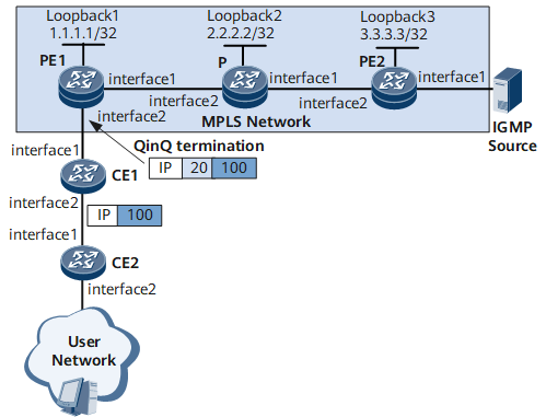
On the network shown in Figure 1, Multicast protocol packets are labeled with an outer tag and an inner tag on CE1 and CE2 respectively, and then sent to PE1. After receiving the packets, PE1 terminates two tags, and then accesses the virtual private LAN service (VPLS) network in an asymmetrical manner. PE2 terminates the pseudowire (PW), joins the related multicast VLAN, and accesses the multicast source.
PE2 functions as a Superstratum PE (SPE) device, and PE1 functions an Underlayer PE (UPE) device. When the hierarchical virtual private LAN service (HVPLS) is deployed, multicast packets are broadcast in a virtual switching instance (VSI) if PE1 and PE2 do not support IGMP snooping. This wastes network resources.
After IGMP snooping is configured, multicast packets are sent to only access devices of multicast receivers.
On the network with a stable topology, the PW on PE1 is configured as a static router interface in the VSI. Therefore, receivers can steadily receive multicast data.
To reduce the number of IGMP Query packets from the upstream router, you are advised to configure PE2 as a querier. This saves bandwidths.

Interfaces 1 and 2 in this example represent GE 0/1/1 and GE 0/1/2, respectively.
Device |
Interface |
IP Address |
|---|---|---|
PE1 |
GE0/1/2 |
- |
GE0/1/1 |
192.168.12.1/24 |
|
Loopback1 |
1.1.1.1/32 |
|
P |
GE0/1/0 |
192.168.12.2/24 |
GE0/1/1 |
192.168.23.1/24 |
|
Loopback 2 |
2.2.2.2/32 |
|
PE2 |
GE0/1/2 |
192.168.23.2/24 |
GE0/1/1 |
- |
|
Loopback3 |
3.3.3.3/32 |
Configuration Roadmap
The configuration roadmap is as follows:
Configure the termination mode on PE1 to be the user termination mode.
Configure basic VPLS functions.
Enable global IGMP snooping and IGMP snooping for a VSI.
Bind a VSI to an AC interface on PE1 and PE2 respectively.
Configure a PW on PE1, P, and PE2, and PE1, P, and PE2 accesses the VPLS network in asymmetrical mode.
Configure static router ports and configure PE2 as a querier.
Data Preparation
To complete the configuration, you need the following data:
Multicast VLAN ID: 10
CE1's VLAN ID: 20; CE2's VLAN ID: 100
VSI name: v123; VSI ID: 123
PE1's Multiprotocol Label Switching (MPLS) LSR ID: 1.1.1.1; P's MPLS LSR ID: 2.2.2.2; PE2's MPLS LSR ID: 1.1.1.1
Procedure
- Configure QinQ termination on PE1.
<HUAWEI> system-view
[*HUAWEI] sysname PE1
[*HUAWEI] commit
[~PE1] interface gigabitethernet 0/1/2.1
[*PE1-GigabitEthernet0/1/2.1] control-vid 10 qinq-termination
[*PE1-GigabitEthernet0/1/2.1] qinq termination l2 asymmetry
[*PE1-GigabitEthernet0/1/2.1] qinq termination pe-vid 20 ce-vid 100
[*PE1-GigabitEthernet0/1/2.1] commit
[~PE1-GigabitEthernet0/1/2.1] quit
- Configure an IGP on the MPLS backbone network. In this example, OSPF is adopted to advertise routes. When configuring OSPF, advertise the 32-bit loopback interface addresses of PE1 and PE2.
# Configure PE1.
[*PE1] interface loopback 1
[*PE1-LoopBack1] ip address 1.1.1.1 32
[*PE1-LoopBack1] quit
[*PE1] interface gigabitethernet 0/1/1
[*PE1-GigabitEthernet0/1/1] ip address 192.168.12.1 24
[*PE1-GigabitEthernet0/1/1] undo shutdown
[*PE1-GigabitEthernet0/1/1] quit
[*PE1] ospf
[*PE1-ospf-1] area 0
[*PE1-ospf-1-area-0.0.0.0] network 1.1.1.1 0.0.0.0
[*PE1-ospf-1-area-0.0.0.0] network 192.168.12.0 0.0.0.255
[*PE1-ospf-1-area-0.0.0.0] quit
[*PE1-ospf-1] commit
[~PE1-ospf-1] quit
# Configure P.
<HUAWEI> system-view
[*HUAWEI] sysname P
[*HUAWEI] commit
[~P] interface loopback 2
[*P-LoopBack2] ip address 2.2.2.2 32
[*P-LoopBack2] quit
[*P] interface gigabitethernet 0/1/0
[*P-GigabitEthernet0/1/0] ip address 192.168.12.2 24
[*P-GigabitEthernet0/1/0] undo shutdown
[*P-GigabitEthernet0/1/0] quit
[*P] interface gigabitethernet 0/1/1
[*P-GigabitEthernet0/1/1] ip address 192.168.23.1 24
[*P-GigabitEthernet0/1/1] undo shutdown
[*P-GigabitEthernet0/1/1] quit
[*P] ospf
[*P-ospf-1] area 0
[*P-ospf-1-area-0.0.0.0] network 2.2.2.2 0.0.0.0
[*P-ospf-1-area-0.0.0.0] network 192.168.12.0 0.0.0.255
[*P-ospf-1-area-0.0.0.0] network 192.168.23.0 0.0.0.255
[*P-ospf-1-area-0.0.0.0] quit
[*P-ospf-1] commit
[~P-ospf-1] quit
# Configure PE2.
<HUAWEI> system-view
[*HUAWEI] sysname PE2
[*HUAWEI] commit
[~PE2] interface loopback 3
[*PE2-LoopBack3] ip address 3.3.3.3 32
[*PE2-LoopBack3]quit
[*PE2] interface gigabitethernet 0/1/2
[*PE2-GigabitEthernet0/1/2] ip address 192.168.23.2 24
[*PE2-GigabitEthernet0/1/2] undo shutdown
[*PE2-GigabitEthernet0/1/2] quit
[*PE2] ospf
[*PE2-ospf-1] area 0
[*PE2-ospf-1-area-0.0.0.0] network 3.3.3.3 0.0.0.0
[*PE2-ospf-1-area-0.0.0.0] network 192.168.23.0 0.0.0.255
[*PE2-ospf-1-area-0.0.0.0] quit
[*PE2-ospf-1] commit
[~PE2-ospf-1] quit
- Configure basic MPLS functions and LDP.
# Configure PE1.
[*PE1] mpls lsr-id 1.1.1.1
[*PE1] mpls
[*PE1-mpls] quit
[*PE1] mpls ldp
[*PE1-mpls-ldp] quit
[*PE1] interface gigabitethernet 0/1/1
[*PE1-GigabitEthernet0/1/1] mpls
[*PE1-GigabitEthernet0/1/1] mpls ldp
[*PE1-GigabitEthernet0/1/1]commit
[~PE1-GigabitEthernet0/1/1]quit
# Configure PE2.
[*PE2] mpls lsr-id 3.3.3.3
[*PE2] mpls
[*PE2-mpls] quit
[*PE2] mpls ldp
[*PE2-mpls-ldp] quit
[*PE2] interface gigabitethernet 0/1/2
[*PE2-GigabitEthernet0/1/2] mpls
[*PE2-GigabitEthernet0/1/2] mpls ldp
[*PE2-GigabitEthernet0/1/2]commit
[~PE2-GigabitEthernet0/1/2]quit
# Configure P.
[*P] mpls lsr-id 2.2.2.2
[*P] mpls
[*P-mpls] quit
[*P] mpls ldp
[*P-mpls-ldp] quit
[*P] interface gigabitethernet 0/1/0
[*P-GigabitEthernet0/1/0] mpls
[*P-GigabitEthernet0/1/0] mpls ldp
[*P-GigabitEthernet0/1/0] quit
[*P] interface gigabitethernet 0/1/1
[*P-GigabitEthernet0/1/1] mpls
[*P-GigabitEthernet0/1/1] mpls ldp
[*P-GigabitEthernet0/1/1] commit
[~P-GigabitEthernet0/1/1] quit
- Enable MPLS L2VPN and configure a VSI.
# Configure PE1.
[*PE1] mpls l2vpn
[*PE1-l2vpn] quit
[*PE1] vsi v123 static
[*PE1-vsi-v123] pwsignal ldp
[*PE1-vsi-v123-ldp] vsi-id 123
[*PE1-vsi-v123-ldp] peer 3.3.3.3
[*PE1-vsi-v123-ldp] quit
[*PE1-vsi-v123] commit
[~PE1-vsi-v123] quit
# Configure PE2.
[*PE2] mpls l2vpn
[*PE2-l2vpn] quit
[*PE2] vsi v123 static
[*PE2-vsi-v123] pwsignal ldp
[*PE2-vsi-v123-ldp] vsi-id 123
[*PE2-vsi-v123-ldp] peer 1.1.1.1 upe
[*PE2-vsi-v123-ldp] quit
[*PE2-vsi-v123] commit
[~PE2-vsi-v123] quit
- Configure remote MPLS LDP sessions for PE1 and PE2.
# Configure PE1.
[*PE1] mpls ldp remote-peer PE2
[*PE1-mpls-ldp-remote-PE2] remote-ip 3.3.3.3
[*PE1-mpls-ldp-remote-PE2] commit
[~PE1-mpls-ldp-remote-PE2] quit
# Configure PE2.
[*PE2] mpls ldp remote-peer PE1
[*PE2-mpls-ldp-remote-PE1] remote-ip 1.1.1.1
[*PE2-mpls-ldp-remote-PE1] commit
[~PE2-mpls-ldp-remote-PE1] quit
- Bind the interface to the VSI on a PE.
# Configure PE1. The configurations of GE 0/1/1 on PE2 are similar to the configuration of PE1, and are not mentioned here.
[*PE1] vlan 10
[*PE1-vlan10] quit
[*PE1] interface gigabitethernet 0/1/2.1
[*PE1-GigabitEthernet0/1/2.1] l2 binding vsi v123
[*PE1-GigabitEthernet0/1/2.1] commit
[~PE1-GigabitEthernet0/1/2.1] quit
- Enable global IGMP snooping on the PE1 and PE2 and IGMP snooping in the VSI.
# Configure PE1. The configurations of PE2 are similar to the configuration of PE1 and are not mentioned here.
[*PE1] igmp-snooping enable
[*PE1] vsi v123
[*PE1-vsi-v123] igmp-snooping enable
[*PE1-vsi-v123] igmp-snooping version 3
[*PE1-vsi-v123] commit
[~PE1-vsi-v123] quit
- Configure the PW on PE1 as a static router port, and configure the querier on PE2. The default values are used for the querier and therefore no special configuration is required.
# Configure PE1.
[*PE1] vsi v123
[*PE1-vsi-v123] igmp-snooping static-router-port remote-peer 3.3.3.3
[*PE1-vsi-v123] commit
[~PE1-vsi-v123] quit
[*PE1] quit
# Configure PE2.
[*PE2] igmp-snooping send-query enable
[*PE2] vsi v123
[*PE2-vsi-v123] igmp-snooping querier enable
[*PE2-vsi-v123] quit
[*PE2] interface Gigabitethernet0/1/1
[*PE2-GigabitEthernet0/1/1] portswitch
[*PE2-GigabitEthernet0/1/1] port default vlan 10
[*PE2-GigabitEthernet0/1/1] igmp-snooping static-router-port vlan 10
[*PE2-GigabitEthernet0/1/1] quit
[*PE2] interface Gigabitethernet0/1/1.1
[*PE2-GigabitEthernet0/1/1.1] vlan-type dot1q 11
[*PE2-GigabitEthernet0/1/1.1] l2 binding vsi v123
[*PE2-GigabitEthernet0/1/1.1] igmp-snooping static-router-port vsi v123
[*PE2-GigabitEthernet0/1/1.1] quit
[*PE2] commit
[~PE2] quit
- Verify the configuration.
Run the display qinq information termination interface command on PE1, and you can view information about the configured QinQ sub-interface.
<PE1> display qinq information termination interface gigabitethernet 0/1/2
  GigabitEthernet 0/1/2.1
    VSI bound
    Total QinQ Num: 1
      qinq termination pe-vid 20 ce-vid 100
    Total vlan-group Num: 0
    encapsulation qinq-termination
Run the display mpls ldp session command, and you view that MPLS LDP sessions on PE1, P, and PE2 are in the Operational state.
The following uses the command output on PE1 as an example.
<PE1>display mpls ldp session
 LDP Session(s) in Public Network
 Codes: LAM(Label Advertisement Mode), SsnAge Unit(DDDD:HH:MM)
 An asterisk (*) before a session means the session is being deleted.
--------------------------------------------------------------------------
 PeerID             Status       LAM  SsnRole  SsnAge       KASent/Rcv
--------------------------------------------------------------------------
 2.2.2.2:0          Operational DU   Passive  0000:03:11   767/767
 3.3.3.3:0          Operational DU   Passive  0000:03:05   743/743
--------------------------------------------------------------------------
TOTAL: 2 Session(s) Found.
Run the display igmp-snooping querier vsi command on PE2, and you can check whether the configuration of the querier succeeds. If the Enable state is displayed in the following output, it indicates that the querier is enabled for VSI v123.
<PE2> display igmp-snooping querier vsi v123
VSI                             Querier-state Querier
---------------------------------------------------------------
v123                            Enable       192.168.0.1
Run the display igmp-snooping router-port vsi command on PE1, and you can check whether the configuration of the static router port succeeds. If STATIC is displayed as shown in the following output, it indicates that PW (1.1.1.1/123) is configured as a static router port.
<PE1> display igmp-snooping router-port vsi v123
 Port Name                            UpTime        Expires       Flags
 --------------------------------------------------------------------------
 VSI v123, 1 router-port(s)
 PW(3.3.3.3/123)                      00:49:14      --            STATIC
Run the display igmp-snooping port-info command on PE1, and you can view information about multicast VLAN tags and multicast groups on a specified QinQ interface.
<PE1> display igmp-snooping port-info
 -------------------------------------------------------------------------------
  Flag: S:Static     D:Dynamic     M:Ssm-mapping
        A:Active     P:Protocol    F:Fast-channel
                    (Source, Group)  Port                                      Flag
 -------------------------------------------------------------------------------
 VSI v123, 1 Entry(s)
                (1.1.1.1, 234.1.1.1)                                        P--
                                      GE0/1/2.1(PE:20/CE:100)               S--
                                                        1 port(s) include
 -------------------------------------------------------------------------------
Configuration Files
PE1 configuration file
#
sysname PE1
#
vlan batch 10
#
igmp-snooping enable
igmp-snooping send-query enable
#
mpls lsr-id 1.1.1.1
#
mpls
#
mpls l2vpn
#
vsi v123 static
 pwsignal ldp
  vsi-id 123
  peer 3.3.3.3
 igmp-snooping enable
 igmp-snooping version 3
 igmp-snooping static-router-port remote-peer 3.3.3.3
#
mpls ldp
#
mpls ldp remote-peer pe2
 remote-ip 3.3.3.3
#
interface Gigabitethernet0/1/2.1
 encapsulation qinq-termination
 qinq termination pe-vid 20 ce-vid 100
 l2 binding vsi v123
 l2-multicast static-group source-address 1.1.1.1 group-address 234.1.1.1 qinq pe-vid 20 ce-vid 100 vsi v123
#
interface Gigabitethernet0/1/1
 undo shutdown
 ip address 192.168.12.1 255.255.255.0
 mpls
 mpls ldp
#
interface LoopBack1
 ip address 1.1.1.1 255.255.255.255
#
ospf 1
 area 0.0.0.0
  network 1.1.1.1 0.0.0.0
  network 192.168.12.0 0.0.0.255
#
return
P configuration file
#
sysname P
#
mpls lsr-id 2.2.2.2
#
mpls
#
mpls ldp
#
interface Gigabitethernet0/1/0
 undo shutdown
 ip address 192.168.12.2 255.255.255.0
 mpls
 mpls ldp
#
interface Gigabitethernet0/1/1
 undo shutdown
 ip address 192.168.23.1 255.255.255.0
 mpls
 mpls ldp
#
interface LoopBack2
 ip address 2.2.2.2 255.255.255.255
#
ospf 1
 area 0.0.0.0
  network 2.2.2.2 0.0.0.0
  network 192.168.12.0 0.0.0.255
  network 192.168.23.0 0.0.0.255
#
return
PE2 configuration file
#
sysname PE2
#
vlan batch 10
#
igmp-snooping enable
igmp-snooping send-query enable
#
mpls lsr-id 3.3.3.3
#
mpls
#
mpls l2vpn
#
vsi v123 static
 pwsignal ldp
  vsi-id 123
  peer 1.1.1.1
 igmp-snooping enable
 igmp-snooping querier enable
#
mpls ldp
#
mpls ldp remote-peer pe1
 remote-ip 1.1.1.1
#
interface Gigabitethernet0/1/2
 undo shutdown
 ip address 192.168.23.2 255.255.255.0
 mpls
 mpls ldp
 dcn
#
interface Gigabitethernet0/1/1
 portswitch
 undo shutdown
 port default vlan 10
 igmp-snooping static-router-port vlan 10
#
interface Gigabitethernet0/1/1.1
 vlan-type dot1q 11
 l2 binding vsi v123
 igmp-snooping static-router-port vsi v123
#
interface LoopBack3
 ip address 3.3.3.3 255.255.255.255
#
ospf 1
 area 0.0.0.0
  network 3.3.3.3 0.0.0.0
  network 192.168.23.0 0.0.0.255
#
return
CE1 configuration file
#
 sysname CE1
#
 vlan batch 20
#
interface Gigabitethernet0/1/2
 portswitch
 port vlan-stacking vlan 100 stack-vlan 20
#
interface Gigabitethernet0/1/1
 portswitch
 port trunk allow-pass vlan 20
#
return
CE2 configuration file
#
 sysname CE2
#
 vlan batch 100
#
interface Gigabitethernet0/1/2
 portswitch
 port default vlan 100
#
interface Gigabitethernet0/1/1
 portswitch
 port trunk allow-pass vlan 100
#
return