Example for Configuring Basic RIP Functions
This section describes how to configure basic RIP functions, including how to enable RIP and configure the RIP version number on each device.
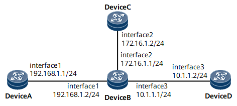
Networking Requirements
On the network shown in Figure 1, it is required that RIP be enabled on all interfaces of Device A, Device B, Device C, and Device D and that the Devices communicate with each other through RIP-2.

Precautions
During the configuration, note the following rules:
Different network segments on the same physical interface must be configured in the same RIP process.
If a RIP process is bound to a VPN instance, the interfaces in this RIP process also need to be bound to this VPN instance.
Configuration Roadmap
The configuration roadmap is as follows:
Configure IP addresses for interfaces to ensure that neighboring nodes are reachable at the network layer.
Enable RIP on each router and configure basic RIP functions.
Configure RIP-2 on each router and view the subnet masks.
Data Preparation
To complete the configuration, you need the following data:
RIP network segment 192.168.1.0 on Device A
RIP network segments 192.168.1.0, 172.16.0.0, and 10.0.0.0 on Device B
RIP network segment 172.16.0.0 on Device C
RIP network segment 10.0.0.0 on Device D
RIP-2 on Device A, Device B, Device C, and Device D
Procedure
- Configure an IP address for each interface.
For configuration details, see Configuration Files in this section.
- Configure a RIP process to import static routes.
- Configure the network segments to be enabled with RIP.
# Configure Device A.
[~DeviceA] rip
[*DeviceA-rip-1] network 192.168.1.0
[*DeviceA-rip-1] commit
[~DeviceA-rip-1] quit
# Configure Device B.
[~DeviceB] rip
[*DeviceB-rip-1] network 192.168.1.0
[*DeviceB-rip-1] network 172.16.0.0
[*DeviceB-rip-1] network 10.0.0.0
[*DeviceB-rip-1] commit
[~DeviceB-rip-1] quit
# Configure Device C.
[~DeviceC] rip
[*DeviceC-rip-1] network 172.16.0.0
[*DeviceC-rip-1] commit
[~DeviceC-rip-1] quit
# Configure Device D.
[~DeviceD] rip
[*DeviceD-rip-1] network 10.0.0.0
[*DeviceD-rip-1] commit
[~DeviceD-rip-1] quit
# Check the RIP routing table of Device A.
[~DeviceA] display rip 1 route
 Route Flags: R - RIP
              A - Aging, S - Suppressed, G - Garbage-collect
-------------------------------------------------------------------------
 Peer 192.168.1.2  on GigabitEthernet0/1/0
      Destination/Mask        Nexthop     Cost   Tag     Flags   Sec
         10.0.0.0/8        192.168.1.2      1    0        RA      14
         172.16.0.0/16     192.168.1.2      1    0        RA      14
The preceding command output shows that the routes advertised by RIP-1 use natural masks.
- Configure the RIP version number.
# Configure RIP-2 on Device A.
[~DeviceA] rip
[~DeviceA-rip-1] version 2
[*DeviceA-rip-1] commit
[~DeviceA-rip-1] quit
# Configure RIP-2 on Device B.
[~DeviceB] rip
[~DeviceB-rip-1] version 2
[*DeviceB-rip-1] commit
[~DeviceB-rip-1] quit
# Configure RIP-2 on Device C.
[~DeviceC] rip
[~DeviceC-rip-1] version 2
[*DeviceC-rip-1] commit
[~DeviceC-rip-1] quit
# Configure RIP-2 on Device D.
[~DeviceD] rip
[~DeviceD-rip-1] version 2
[*DeviceD-rip-1] commit
[~DeviceD-rip-1] quit
- Verify the configuration.
# Check the RIP routing table of Device A.
[~DeviceA] display rip 1 route
Route Flags: R - RIP
             A - Aging, S - Suppressed, G - Garbage-collect
-------------------------------------------------------------------------
 Peer 192.168.1.2  on GigabitEthernet0/1/0
      Destination/Mask        Nexthop       Cost   Tag     Flags   Sec
         10.1.1.0/24         192.168.1.2      1    0        RA      32
         172.16.1.0/24       192.168.1.2      1    0        RA      32
The preceding command output shows that the routes advertised by RIP-2 contain accurate subnet masks.
Configuration Files
Device A configuration file
#
 sysname DeviceA
#
interface GigabitEthernet0/1/0
 undo shutdown
 ip address 192.168.1.1 255.255.255.0
#
rip 1
 version 2
 network 192.168.1.0
#
return
Device B configuration file
#
sysname DeviceB
#
interface GigabitEthernet0/1/0
 undo shutdown
 ip address 192.168.1.2 255.255.255.0
#
interface GigabitEthernet0/1/8
 undo shutdown
 ip address 172.16.1.1 255.255.255.0
#
interface GigabitEthernet0/1/16
 undo shutdown
 ip address 10.1.1.1 255.255.255.0
#
rip 1
 version 2
 network 10.0.0.0
 network 172.16.0.0
 network 192.168.1.0
#
return
Device C configuration file
#
sysname DeviceC
#
interface GigabitEthernet0/1/8
 undo shutdown
 ip address 172.16.1.2 255.255.255.0
#
rip 1
 version 2
 network 172.16.0.0
#
return
Device D configuration file
#
sysname DeviceD
#
interface GigabitEthernet0/1/16
 undo shutdown
 ip address 10.1.1.2 255.255.255.0
#
rip 1
 version 2
 network 10.0.0.0
#
return