RRPP Snooping
RRPP snooping advertises changes on the RRPP ring to the VPLS network. In this case, when RRPP snooping is enabled on sub-interfaces or VLANIF interfaces, the VPLS network can transparently transmit RRPP protocol packets, detect the changes in the RRPP ring, and upgrade the forwarding entries to ensure that traffic can be switched to a non-blocking path.
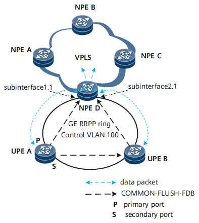
As shown in Figure 3, UPEs are connected to the VPLS network where NPEs reside in the form of RRPP ring. NPEs are connected over a PW, and therefore cannot serve as RRPP nodes to directly respond to RRPP protocol packets. As a result, the VPLS network cannot sense the status change of the RRPP ring. When the RRPP ring topology changes, each node on the VPLS network forwards downstream data according to the MAC address table generated before the RRPP ring topology changes. As a result, the downstream traffic cannot be forwarded.
RRPP snooping is enabled on the sub-interface or VLANIF interface of NPE D and associated with other VSIs on the local device. When the RRPP ring fails, NPE D on the VPLS network clears the forwarding entries of the VSIs (including the associated VSIs) on the local node and the forwarding entries of the remote NPE B to re-learn forwarding entries. This ensures that traffic can be switched to a normal path and downstream traffic will be normally forwarded.
As shown in Figure 2, the link between NPE D and UPE A is faulty, and the RRPP master node UPE A sends a COMMON-FLUSH-FDB packet to notify the transit nodes on the RRPP ring to clear its MAC address table.
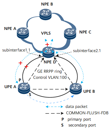
The original MAC address table is not cleared because NPE D cannot process the COMMON-FLUSH-FDB packet. If the downstream data packet sent to UPE A exists, NPE D sends it to UPE A along the original path. This leads to an interruption in downstream traffic between NPE D and NPE A. After UPE B clears its MAC address table, the upstream data packet sent by UPE A is regarded as an unknown unicast packet to be forwarded to the VPLS network along the path UPE A->UPE B->NPE D. After re-learning the MAC address, NPE D can correctly forward the downstream traffic intended for UPE A.
When the RRPP ring fault recovers, UPE A, the master node, sends a COMPLETE-FLUSH-FDB packet to notify the transit node to clear its MAC address table. The downstream traffic between NPE D and UPE A is interrupted because NPE D cannot process the COMPLETE-FLUSH-FDB packet
As shown in Figure 3, after RRPP snooping is enabled on sub-interfaces GE 1/0/0.100 and GE 2/0/0.100 of NPE D, NPE D can process the COMMON-FLUSH-FDB or COMPLETE-FLUSH-FDB packet.
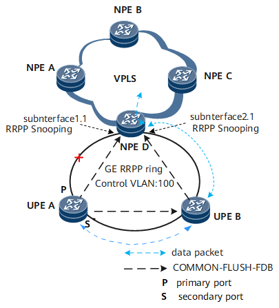
When the RRPP ring topology changes and NPE D receives the COMMON-FLUSH-FDB or COMPLETE-FLUSH-FDB packet from the master node UPE A, NPE D clears the MAC address table of the VSI associated with sub-interfaces GE 1/0/0.100 and GE 2/0/0.100 and then notifies other NPEs in this VSI to clear their MAC address tables also.
If the downstream data packet sent to UPE A exists, this packet is regarded as an unknown unicast packet to be broadcast in the VLAN and sent to UPE A along the path UPE D->UPE B->NPE A because NPE D cannot find the MAC address table. This ensures continuity of downstream traffic.