Example for Configuring Non-Labeled Public BGP Routes to Recurse to an SR-MPLS BE Tunnel
Non-labeled public BGP routes are configured to recurse to an SR-MPLS BE tunnel, so that public network BGP traffic can be transmitted along the SR-MPLS BE tunnel.
Networking Requirements
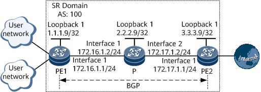
If an Internet user sends packets to a carrier network that performs IP forwarding to access the Internet, core carrier devices on a forwarding path must learn many Internet routes. This imposes a heavy load on the core carrier devices and affects the performance of these devices. To tackle the problems, a user access device can be configured to recurse non-labeled public network BGP or static routes to a Segment Routing (SR) tunnel. User packets travel through the SR tunnel to access the Internet. The recursion to the SR tunnel prevents the problems induced by insufficient performance, heavy burdens, and service transmission on the core devices on the carrier network.
In Figure 1, non-labeled public BGP routes are configured to recurse to an SR-MPLS BE tunnel.
Precautions
During the configuration process, note the following:
When establishing a peer, if the specified IP address of the peer is a loopback interface address or a sub-interface address, you need to run the peer connect-interface command on the two ends of the peer to ensure that the two ends are correctly connected.
Configuration Roadmap
The configuration roadmap is as follows:
Configure IS-IS on the backbone network for the PEs to communicate.
Enable MPLS on the backbone network, configure SR, and establish SR LSPs.
Establish an IBGP peer relationship between the PEs for them to exchange routing information.
Enable PEs to recurse non-labeled public BGP routes to the SR-MPLS BE tunnel.
Data Preparation
To complete the configuration, you need the following data:
MPLS LSR IDs of the PEs and P
SRGB ranges on the PEs and P
Procedure
- Configure IP addresses for interfaces.
# Configure PE1.
<HUAWEI> system-view
[~HUAWEI] sysname PE1
[*HUAWEI] commit
[~PE1] interface loopback 1
[*PE1-LoopBack1] ip address 1.1.1.9 32
[*PE1-LoopBack1] quit
[*PE1] interface gigabitethernet0/1/0
[*PE1-GigabitEthernet0/1/0] ip address 172.16.1.1 24
[*PE1-GigabitEthernet0/1/0] quit
[*PE1] commit
# Configure the P.
<HUAWEI> system-view
[~HUAWEI] sysname P
[*HUAWEI] commit
[~P] interface loopback 1
[*P-LoopBack1] ip address 2.2.2.9 32
[*P-LoopBack1] quit
[*P] interface gigabitethernet0/1/0
[*P-GigabitEthernet0/1/0] ip address 172.16.1.2 24
[*P-GigabitEthernet0/1/0] quit
[*P] interface gigabitethernet0/1/8
[*P-GigabitEthernet0/1/8] ip address 172.17.1.2 24
[*P-GigabitEthernet0/1/8] quit
[*P] commit
# Configure PE2.
<HUAWEI> system-view
[~HUAWEI] sysname PE2
[*HUAWEI] commit
[~PE2] interface loopback 1
[*PE2-LoopBack1] ip address 3.3.3.9 32
[*PE2-LoopBack1] quit
[*PE2] interface gigabitethernet0/1/0
[*PE2-GigabitEthernet0/1/0] ip address 172.17.1.1 24
[*PE2-GigabitEthernet0/1/0] quit
[*PE2] commit
- Configure an IGP on the backbone network for the PEs to communicate. IS-IS is used as an example.
# Configure PE1.
[~PE1] isis 1
[*PE1-isis-1] is-level level-1
[*PE1-isis-1] network-entity 10.0000.0000.0001.00
[*PE1-isis-1] quit
[*PE1] interface loopback 1
[*PE1-LoopBack1] isis enable 1
[*PE1-LoopBack1] quit
[*PE1] interface gigabitethernet0/1/0
[*PE1-GigabitEthernet0/1/0] isis enable 1
[*PE1-GigabitEthernet0/1/0] quit
[*PE1] commit
# Configure the P.
[~P] isis 1
[*P-isis-1] is-level level-1
[*P-isis-1] network-entity 10.0000.0000.0002.00
[*P-isis-1] quit
[*P] interface loopback 1
[*P-LoopBack1] isis enable 1
[*P-LoopBack1] quit
[*P] interface gigabitethernet0/1/0
[*P-GigabitEthernet0/1/0] isis enable 1
[*P-GigabitEthernet0/1/0] quit
[*P] interface gigabitethernet0/1/8
[*P-GigabitEthernet0/1/8] isis enable 1
[*P-GigabitEthernet0/1/8] quit
[*P] commit
# Configure PE2.
[~PE2] isis 1
[*PE2-isis-1] is-level level-1
[*PE2-isis-1] network-entity 10.0000.0000.0003.00
[*PE2-isis-1] quit
[*PE2] interface loopback 1
[*PE2-LoopBack1] isis enable 1
[*PE2-LoopBack1] quit
[*PE2] interface gigabitethernet0/1/0
[*PE2-GigabitEthernet0/1/0] isis enable 1
[*PE2-GigabitEthernet0/1/0] quit
[*PE2] commit
- (Optional) Configure basic MPLS functions on the backbone network.
MPLS is automatically enabled on the interface where IS-IS has been enabled. Therefore, you can skip this step.
# Configure PE1.
[~PE1] mpls lsr-id 1.1.1.9
[*PE1] mpls
[*PE1-mpls] commit
[~PE1-mpls] quit
# Configure the P.
[~P] mpls lsr-id 2.2.2.9
[*P] mpls
[*P-mpls] commit
[~P-mpls] quit
# Configure PE2.
[~PE2] mpls lsr-id 3.3.3.9
[*PE2] mpls
[*PE2-mpls] commit
[~PE2-mpls] quit
- Configure Segment Routing on the backbone network.
# Configure PE1.
[~PE1] segment-routing
[*PE1-segment-routing] tunnel-prefer segment-routing
[*PE1-segment-routing] quit
[*PE1] isis 1
[*PE1-isis-1] cost-style wide
[*PE1-isis-1] segment-routing mpls
[*PE1-isis-1] segment-routing global-block 160000 161000

The SRGB range varies according to the device. The range specified in this example is for reference only.
[*PE1-isis-1] quit
[*PE1] interface loopback 1
[*PE1-LoopBack1] isis prefix-sid index 10
[*PE1-LoopBack1] quit
[*PE1] commit
# Configure the P.
[~P] segment-routing
[*P-segment-routing] tunnel-prefer segment-routing
[*P-segment-routing] quit
[*P] isis 1
[*P-isis-1] cost-style wide
[*P-isis-1] segment-routing mpls
[*P-isis-1] segment-routing global-block 160000 161000
The SRGB range varies according to the device. The range specified in this example is for reference only.
[*P-isis-1] quit
[*P] interface loopback 1
[*P-LoopBack1] isis prefix-sid index 20
[*P-LoopBack1] quit
[*P] commit
# Configure PE2.
[~PE2] segment-routing
[*PE2-segment-routing] tunnel-prefer segment-routing
[*PE2-segment-routing] quit
[*PE2] isis 1
[*PE2-isis-1] cost-style wide
[*PE2-isis-1] segment-routing mpls
[*PE2-isis-1] segment-routing global-block 160000 161000
The SRGB range varies according to the device. The range specified in this example is for reference only.
[*PE2-isis-1] quit
[*PE2] interface loopback 1
[*PE2-LoopBack1] isis prefix-sid index 30
[*PE2-LoopBack1] quit
[*PE2] commit
- Establish an IBGP peer relationship between the PEs.
# Configure PE1.
[~PE1] bgp 100
[*PE1-bgp] peer 3.3.3.9 as-number 100
[*PE1-bgp] peer 3.3.3.9 connect-interface loopback 1
[*PE1-bgp] commit
[~PE1-bgp] quit
# Configure PE2.
[~PE2] bgp 100
[*PE2-bgp] peer 1.1.1.9 as-number 100
[*PE2-bgp] peer 1.1.1.9 connect-interface loopback 1
[*PE2-bgp] commit
[~PE2-bgp] quit
After the configuration is complete, run the display bgp peer command on the PEs to check whether the BGP peer relationship has been established. If the Established state is displayed in the command output, the BGP peer relationship has been established successfully. The following example uses the command output on PE1.
[~PE1] display bgp peer BGP local router ID : 1.1.1.9 Local AS number : 100 Total number of peers : 1 Peers in established state : 1 Peer V AS MsgRcvd MsgSent OutQ Up/Down State PrefRcv 3.3.3.9 4 100 2 6 0 00:00:12 Established 0 - Enable PEs to recurse non-labeled public BGP routes to the SR-MPLS BE tunnel.
# Configure PE1.
[~PE1] tunnel-policy p1
[*PE1-tunnel-policy-p1] tunnel select-seq sr-lsp load-balance-number 1
[*PE1-tunnel-policy-p1] quit
[*PE1] tunnel-selector s1 permit node 10
[*PE1-tunnel-selector] apply tunnel-policy p1
[*PE1-tunnel-selector] quit
[*PE1] bgp 100
[*PE1-bgp] unicast-route recursive-lookup tunnel tunnel-selector s1
[*PE1-bgp] commit
[~PE1-bgp] quit
# Configure PE2.
[~PE2] tunnel-policy p1
[*PE2-tunnel-policy-p1] tunnel select-seq sr-lsp load-balance-number 1
[*PE2-tunnel-policy-p1] quit
[*PE2] tunnel-selector s1 permit node 10
[*PE2-tunnel-selector] apply tunnel-policy p1
[*PE2-tunnel-selector] quit
[*PE2] bgp 100
[*PE2-bgp] unicast-route recursive-lookup tunnel tunnel-selector s1
[*PE2-bgp] commit
[~PE2-bgp] quit
Configuration Files
PE1 configuration file
#
sysname PE1
#
tunnel-selector s1 permit node 10
 apply tunnel-policy p1
#
mpls lsr-id 1.1.1.9
#
mpls
#
segment-routing
 tunnel-prefer segment-routing
#
isis 1
 is-level level-1
 cost-style wide
 network-entity 10.0000.0000.0001.00
 segment-routing mpls
 segment-routing global-block 160000 161000
#
interface GigabitEthernet0/1/0
 undo shutdown
 ip address 172.16.1.1 255.255.255.0
 isis enable 1
#
interface LoopBack1
 ip address 1.1.1.9 255.255.255.255
 isis enable 1
 isis prefix-sid index 10
#
bgp 100
 peer 3.3.3.9 as-number 100
 peer 3.3.3.9 connect-interface LoopBack1
 #
 ipv4-family unicast
  undo synchronization
  unicast-route recursive-lookup tunnel tunnel-selector s1
  peer 3.3.3.9 enable
#
tunnel-policy p1
 tunnel select-seq sr-lsp load-balance-number 1
#
return
P configuration file
#
sysname P
#
mpls lsr-id 2.2.2.9
#
mpls
#
segment-routing
 tunnel-prefer segment-routing
#
isis 1
 is-level level-1
 cost-style wide
 network-entity 10.0000.0000.0002.00
 segment-routing mpls
 segment-routing global-block 160000 161000
#
interface GigabitEthernet0/1/0
 undo shutdown
 ip address 172.16.1.2 255.255.255.0
 isis enable 1
#
interface GigabitEthernet0/1/8
 undo shutdown
 ip address 172.17.1.2 255.255.255.0
 isis enable 1
#
interface LoopBack1
 ip address 2.2.2.9 255.255.255.255
 isis enable 1
 isis prefix-sid index 20
#
return
PE2 configuration file
#
sysname PE2
#
tunnel-selector s1 permit node 10
 apply tunnel-policy p1
#
mpls lsr-id 3.3.3.9
#
mpls
#
segment-routing
 tunnel-prefer segment-routing
#
isis 1
 is-level level-1
 cost-style wide
 network-entity 10.0000.0000.0003.00
 segment-routing mpls
 segment-routing global-block 160000 161000
#
interface GigabitEthernet0/1/0
 undo shutdown
 ip address 172.17.1.1 255.255.255.0
 isis enable 1
#
interface LoopBack1
 ip address 3.3.3.9 255.255.255.255
 isis enable 1
 isis prefix-sid index 30
#
bgp 100
 peer 1.1.1.9 as-number 100
 peer 1.1.1.9 connect-interface LoopBack1
 #
 ipv4-family unicast
  undo synchronization
  unicast-route recursive-lookup tunnel tunnel-selector s1
  peer 1.1.1.9 enable
#
tunnel-policy p1
 tunnel select-seq sr-lsp load-balance-number 1
#
return