Example for Configuring IS-IS SR to Communicate with LDP
This section provides an example for configuring IS-IS SR to communicate with LDP so that devices in the SR domain can communicate with devices in the LDP domain using MPLS forwarding techniques.
Networking Requirements
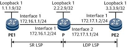
As shown in Figure 1, an SR domain is created between PE1 and P, and an LDP domain lies between P and PE2. PE1 and PE2 need to communicate with each other.
Precautions
When configuring IS-IS SR to communicate with LDP, note that a device in the SR domain must be able to map LDP prefix information to SR SIDs.
Configuration Roadmap
The configuration roadmap is as follows:
Enable IS-IS on the backbone network to ensure that PEs interwork with each other.
Enable MPLS on the backbone network. Configure segment routing to establish an SR LSP from PE1 to the P. Configure LDP to establish an LDP LSP from the P to PE2.
Configure the mapping server function on the P to map LDP prefix information to SR SIDs.
Data Preparation
To complete the configuration, you need the following data:
MPLS LSR IDs of the PEs and P
SRGB ranges on the PE1 and P
Procedure
- Configure IP addresses for interfaces.
# Configure PE1.
<HUAWEI> system-view
[~HUAWEI] sysname PE1
[*HUAWEI] commit
[~PE1] interface loopback 1
[*PE1-LoopBack1] ip address 1.1.1.9 32
[*PE1-LoopBack1] quit
[*PE1] interface gigabitethernet0/1/0
[*PE1-GigabitEthernet0/1/0] ip address 172.16.1.1 24
[*PE1-GigabitEthernet0/1/0] quit
[*PE1] commit
# Configure the P.
<HUAWEI> system-view
[~HUAWEI] sysname P
[*HUAWEI] commit
[~P] interface loopback 1
[*P-LoopBack1] ip address 2.2.2.9 32
[*P-LoopBack1] quit
[*P] interface gigabitethernet0/1/0
[*P-GigabitEthernet0/1/0] ip address 172.16.1.2 24
[*P-GigabitEthernet0/1/0] quit
[*P] interface gigabitethernet0/1/8
[*P-GigabitEthernet0/1/8] ip address 172.17.1.1 24
[*P-GigabitEthernet0/1/8] quit
[*P] commit
# Configure PE2.
<HUAWEI> system-view
[~HUAWEI] sysname PE2
[*HUAWEI] commit
[~PE2] interface loopback 1
[*PE2-LoopBack1] ip address 3.3.3.9 32
[*PE2-LoopBack1] quit
[*PE2] interface gigabitethernet0/1/0
[*PE2-GigabitEthernet0/1/0] ip address 172.17.1.2 24
[*PE2-GigabitEthernet0/1/0] quit
[*PE2] commit
- Configure an IGP protocol on the MPLS backbone network to implement connectivity between the PEs.
IS-IS is used as an IGP protocol in this example.
# Configure PE1.
[~PE1] isis 1
[*PE1-isis-1] is-level level-1
[*PE1-isis-1] cost-style wide
[*PE1-isis-1] network-entity 10.0000.0000.0001.00
[*PE1-isis-1] quit
[*PE1] interface loopback 1
[*PE1-LoopBack1] isis enable 1
[*PE1-LoopBack1] quit
[*PE1] interface gigabitethernet0/1/0
[*PE1-GigabitEthernet0/1/0] isis enable 1
[*PE1-GigabitEthernet0/1/0] quit
[*PE1] commit
# Configure the P.
[~P] isis 1
[*P-isis-1] is-level level-1
[*P-isis-1] cost-style wide
[*P-isis-1] network-entity 10.0000.0000.0002.00
[*P-isis-1] quit
[*P] interface loopback 1
[*P-LoopBack1] isis enable 1
[*P-LoopBack1] quit
[*P] interface gigabitethernet0/1/0
[*P-GigabitEthernet0/1/0] isis enable 1
[*P-GigabitEthernet0/1/0] quit
[*P] interface gigabitethernet0/1/8
[*P-GigabitEthernet0/1/8] isis enable 1
[*P-GigabitEthernet0/1/8] quit
[*P] commit
# Configure PE2.
[~PE2] isis 1
[*PE2-isis-1] is-level level-1
[*PE2-isis-1] cost-style wide
[*PE2-isis-1] network-entity 10.0000.0000.0003.00
[*PE2-isis-1] quit
[*PE2] interface loopback 1
[*PE2-LoopBack1] isis enable 1
[*PE2-LoopBack1] quit
[*PE2] interface gigabitethernet0/1/0
[*PE2-GigabitEthernet0/1/0] isis enable 1
[*PE2-GigabitEthernet0/1/0] quit
[*PE2] commit
- Configure the basic MPLS functions on the MPLS backbone network.
# Configure PE1.
[~PE1] mpls lsr-id 1.1.1.9
[*PE1] mpls
[*PE1-mpls] commit
[~PE1-mpls] quit
# Configure the P.
[~P] mpls lsr-id 2.2.2.9
[*P] mpls
[*P-mpls] quit
[*P] interface gigabitethernet0/1/8
[*P-GigabitEthernet0/1/8] mpls
[*P-GigabitEthernet0/1/8] quit
[*P] commit
# Configure PE2.
[~PE2] mpls lsr-id 3.3.3.9
[*PE2] mpls
[*PE2-mpls] quit
[*PE2] interface gigabitethernet0/1/0
[*PE2-GigabitEthernet0/1/0] mpls
[*PE2-GigabitEthernet0/1/0] quit
[*PE2] commit
- Configure segment routing between PE1 and the P on the backbone network.
# Configure PE1.
[~PE1] segment-routing
[*PE1-segment-routing] tunnel-prefer segment-routing
[*PE1-segment-routing] quit
[*PE1] isis 1
[*PE1-isis-1] segment-routing mpls
[*PE1-isis-1] segment-routing global-block 160000 161000

The SRGB range varies according to the device. The range specified in this example is for reference only.
[*PE1-isis-1] quit
[*PE1] interface loopback 1
[*PE1-LoopBack1] isis prefix-sid index 10
[*PE1-LoopBack1] quit
[*PE1] commit
# Configure the P.
[~P] segment-routing
[*P-segment-routing] tunnel-prefer segment-routing
[*P-segment-routing] quit
[*P] isis 1
[*P-isis-1] segment-routing mpls
[*P-isis-1] segment-routing global-block 160000 161000
The SRGB range varies according to the device. The range specified in this example is for reference only.
[*P-isis-1] quit
[*P] interface loopback 1
[*P-LoopBack1] isis prefix-sid index 20
[*P-LoopBack1] quit
[*P] commit
- Establish an LDP LSP between PE2 and the P.
# Configure the P.
[~P] mpls ldp
[*P-mpls-ldp] quit
[*P] interface gigabitethernet0/1/8
[*P-GigabitEthernet0/1/8] mpls ldp
[*P-GigabitEthernet0/1/8] quit
[*P] commit
# Configure PE2.
[~PE2] mpls ldp
[*PE2-mpls-ldp] quit
[*PE2] interface gigabitethernet0/1/0
[*PE2-GigabitEthernet0/1/0] mpls ldp
[*PE2-GigabitEthernet0/1/0] quit
[*PE2] commit
- Configure the mapping server function on the P, and configure the P to allow SR and LDP to communicate with each other.
# Configure the P.
[~P] segment-routing
[~P-segment-routing] mapping-server prefix-sid-mapping 3.3.3.9 32 22
[*P-segment-routing] quit
[*P] isis 1
[*P-isis-1] segment-routing mapping-server send
[*P-isis-1] quit
[*P] mpls
[*P-mpls] lsp-trigger segment-routing-interworking best-effort host
[*P-mpls] commit
[~P-mpls] quit
- Verify the configuration.
Run the display segment-routing prefix mpls forwarding command on an SR device to check information about the label forwarding table for segment routing.
# In the following, the command output on the P is used.
[~P] display segment-routing prefix mpls forwarding
                         Segment Routing Prefix MPLS Forwarding Information
                   --------------------------------------------------------------
                   Role : I-Ingress, T-Transit, E-Egress, I&T-Ingress And Transit

Prefix          Label      OutLabel   Interface       NextHop        Role   MPLSMtu   Mtu   State
-----------------------------------------------------------------------------------------------------
3.3.3.9/32      160022     NULL       Mapping LDP     ---            E      ---       ---   Active

Total information(s): 1
The command output shows that the forwarding entry for the route to 3.3.3.9/32 exists and has its outbound interface is the mapping LDP, which indicates that the P has successfully stitched the SR LSP to the MPLS LDP LSP.
# Configure the PEs to ping each other. For example, PE1 pings PE2 at 3.3.3.9.
[~PE1] ping lsp segment-routing ip 3.3.3.9 32 version draft2 remote 3.3.3.9
 LSP PING FEC: Nil FEC : 100  data bytes, press CTRL_C to break
    Reply from 3.3.3.9: bytes=100 Sequence=1 time=72 ms
    Reply from 3.3.3.9: bytes=100 Sequence=2 time=34 ms
    Reply from 3.3.3.9: bytes=100 Sequence=3 time=50 ms
    Reply from 3.3.3.9: bytes=100 Sequence=4 time=50 ms
    Reply from 3.3.3.9: bytes=100 Sequence=5 time=34 ms
  --- FEC: Nil FEC ping statistics ---
    5 packet(s) transmitted
    5 packet(s) received
    0.00% packet loss
    round-trip min/avg/max = 34/48/72 ms
Configuration Files
PE1 configuration file
#
sysname PE1
#
mpls lsr-id 1.1.1.9
#
mpls
#
segment-routing
 tunnel-prefer segment-routing
#
isis 1
 cost-style wide
 network-entity 10.0000.0000.0001.00
 segment-routing mpls
 segment-routing global-block 160000 161000
#
interface GigabitEthernet0/1/0
 undo shutdown
 ip address 172.16.1.1 255.255.255.0
 isis enable 1
#
interface LoopBack1
 ip address 1.1.1.9 255.255.255.255
 isis enable 1
 isis prefix-sid index 10
#
return
P configuration file
#
sysname P
#
mpls lsr-id 2.2.2.9
#
mpls
 lsp-trigger segment-routing-interworking best-effort host
#
mpls ldp
#
segment-routing
 tunnel-prefer segment-routing
 mapping-server prefix-sid-mapping 3.3.3.9 32 22
#
isis 1
 cost-style wide
 network-entity 10.0000.0000.0002.00
 segment-routing mpls
 segment-routing global-block 160000 161000
 segment-routing mapping-server send
#
interface GigabitEthernet0/1/0
 undo shutdown
 ip address 172.16.1.2 255.255.255.0
 isis enable 1
#
interface GigabitEthernet0/1/8
 undo shutdown
 ip address 172.17.1.1 255.255.255.0
 isis enable 1
 mpls
 mpls ldp
#
interface LoopBack1
 ip address 2.2.2.9 255.255.255.255
 isis enable 1
 isis prefix-sid index 20
#
return
PE2 configuration file
#
sysname PE2
#
mpls lsr-id 3.3.3.9
#
mpls
#
mpls ldp
#
isis 1
 cost-style wide
 network-entity 10.0000.0000.0003.00
#
interface GigabitEthernet0/1/0
 undo shutdown
 ip address 172.17.1.2 255.255.255.0
 isis enable 1
 mpls
 mpls ldp
#
interface LoopBack1
 ip address 3.3.3.9 255.255.255.255
 isis enable 1
#
return