Example for Configuring SBFD to Monitor SR-MPLS BE Tunnels
This section provides an example for configuring SBFD to monitor SR-MPLS BE tunnels, which improves network reliability.
Networking Requirements
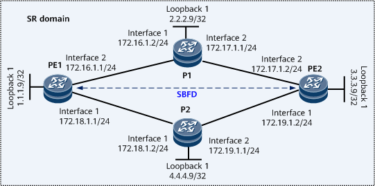
As shown in Figure 1, SR-MPLS BE tunnels are established between PEs on the public network. To improve network reliability, configure SBFD. SBFD can be used to monitor the SR-MPLS BE tunnels. If the primary tunnel fails, applications such as VPN FRR are instructed to quickly switch traffic, minimizing the impact on services.
Configuration Roadmap
The configuration roadmap is as follows:
Enable IS-IS on the backbone network to ensure that PEs interwork with each other.
Configure MPLS and Segment Routing on the backbone network to establish SR LSPs. Enable topology independent-loop free alternate (TI-LFA) FRR.
Configure SBFD to establish sessions between PEs to monitor SR-MPLS BE tunnels.
Data Preparation
To complete the configuration, you need the following data:
MPLS LSR IDs of the PEs and P
SRGB ranges on the PEs and P
Procedure
- Assign an IP address to each interface.
# Configure PE1.
<HUAWEI> system-view
[~HUAWEI] sysname PE1
[*HUAWEI] commit
[~PE1] interface loopback 1
[*PE1-LoopBack1] ip address 1.1.1.9 32
[*PE1-LoopBack1] quit
[*PE1] interface gigabitethernet0/1/0
[*PE1-GigabitEthernet0/1/0] ip address 172.18.1.1 24
[*PE1-GigabitEthernet0/1/0] quit
[*PE1] interface gigabitethernet0/1/8
[*PE1-GigabitEthernet0/1/8] ip address 172.16.1.1 24
[*PE1-GigabitEthernet0/1/8] quit
[*PE1] commit
# Configure P1.
<HUAWEI> system-view
[~HUAWEI] sysname P1
[*HUAWEI] commit
[~P1] interface loopback 1
[*P1-LoopBack1] ip address 2.2.2.9 32
[*P1-LoopBack1] quit
[*P1] interface gigabitethernet0/1/0
[*P1-GigabitEthernet0/1/0] ip address 172.16.1.2 24
[*P1-GigabitEthernet0/1/0] quit
[*P1] interface gigabitethernet0/1/8
[*P1-GigabitEthernet0/1/8] ip address 172.17.1.1 24
[*P1-GigabitEthernet0/1/8] quit
[*P1] commit
# Configure PE2.
<HUAWEI> system-view
[~HUAWEI] sysname PE2
[*HUAWEI] commit
[~PE2] interface loopback 1
[*PE2-LoopBack1] ip address 3.3.3.9 32
[*PE2-LoopBack1] quit
[*PE2] interface gigabitethernet0/1/0
[*PE2-GigabitEthernet0/1/0] ip address 172.19.1.2 24
[*PE2-GigabitEthernet0/1/0] quit
[*PE2] interface gigabitethernet0/1/8
[*PE2-GigabitEthernet0/1/8] ip address 172.17.1.2 24
[*PE2-GigabitEthernet0/1/8] quit
[*PE2] commit
# Configure P2.
<HUAWEI> system-view
[~HUAWEI] sysname P2
[*HUAWEI] commit
[~P2] interface loopback 1
[*P2-LoopBack1] ip address 4.4.4.9 32
[*P2-LoopBack1] quit
[*P2] interface gigabitethernet0/1/0
[*P2-GigabitEthernet0/1/0] ip address 172.18.1.2 24
[*P2-GigabitEthernet0/1/0] quit
[*P2] interface gigabitethernet0/1/8
[*P2-GigabitEthernet0/1/8] ip address 172.19.1.1 24
[*P2-GigabitEthernet0/1/8] quit
[*P2] commit
- Configure an IGP on the backbone network to enable the PEs to communicate. IS-IS is used as an example.
# Configure PE1.
[~PE1] isis 1
[*PE1-isis-1] is-level level-1
[*PE1-isis-1] network-entity 10.0000.0000.0001.00
[*PE1-isis-1] quit
[*PE1] interface loopback 1
[*PE1-LoopBack1] isis enable 1
[*PE1-LoopBack1] quit
[*PE1] interface gigabitethernet0/1/0
[*PE1-GigabitEthernet0/1/0] isis enable 1
[*PE1-GigabitEthernet0/1/0] quit
[*PE1] interface gigabitethernet0/1/8
[*PE1-GigabitEthernet0/1/8] isis enable 1
[*PE1-GigabitEthernet0/1/8] quit
[*PE1] commit
# Configure P1.
[~P1] isis 1
[*P1-isis-1] is-level level-1
[*P1-isis-1] network-entity 10.0000.0000.0002.00
[*P1-isis-1] quit
[*P1] interface loopback 1
[*P1-LoopBack1] isis enable 1
[*P1-LoopBack1] quit
[*P1] interface gigabitethernet0/1/0
[*P1-GigabitEthernet0/1/0] isis enable 1
[*P1-GigabitEthernet0/1/0] quit
[*P1] interface gigabitethernet0/1/8
[*P1-GigabitEthernet0/1/8] isis enable 1
[*P1-GigabitEthernet0/1/8] quit
[*P1] commit
# Configure PE2.
[~PE2] isis 1
[*PE2-isis-1] is-level level-1
[*PE2-isis-1] network-entity 10.0000.0000.0003.00
[*PE2-isis-1] quit
[*PE2] interface loopback 1
[*PE2-LoopBack1] isis enable 1
[*PE2-LoopBack1] quit
[*PE2] interface gigabitethernet0/1/8
[*PE2-GigabitEthernet0/1/8] isis enable 1
[*PE2-GigabitEthernet0/1/8] quit
[*PE2] interface gigabitethernet0/1/0
[*PE2-GigabitEthernet0/1/0] isis enable 1
[*PE2-GigabitEthernet0/1/0] quit
[*PE2] commit
# Configure P2.
[~P2] isis 1
[*P2-isis-1] is-level level-1
[*P2-isis-1] network-entity 10.0000.0000.0004.00
[*P2-isis-1] quit
[*P2] interface loopback 1
[*P2-LoopBack1] isis enable 1
[*P2-LoopBack1] quit
[*P2] interface gigabitethernet0/1/0
[*P2-GigabitEthernet0/1/0] isis enable 1
[*P2-GigabitEthernet0/1/0] quit
[*P2] interface gigabitethernet0/1/8
[*P2-GigabitEthernet0/1/8] isis enable 1
[*P2-GigabitEthernet0/1/8] quit
[*P2] commit
- (Optional) Configure basic MPLS functions on the backbone network.
MPLS is automatically enabled on the interface where IS-IS has been enabled. Therefore, you can skip this step.
# Configure PE1.
[~PE1] mpls lsr-id 1.1.1.9
[*PE1] mpls
[*PE1-mpls] commit
[~PE1-mpls] quit
# Configure P1.
[~P1] mpls lsr-id 2.2.2.9
[*P1] mpls
[*P1-mpls] commit
[~P1-mpls] quit
# Configure PE2.
[~PE2] mpls lsr-id 3.3.3.9
[*PE2] mpls
[*PE2-mpls] commit
[~PE2-mpls] quit
# Configure P2.
[~P2] mpls lsr-id 4.4.4.9
[*P2] mpls
[*P2-mpls] commit
[~P2-mpls] quit
- Configure SR on the backbone network and enable TI-LFA FRR.
# Configure PE1.
[~PE1] segment-routing
[*PE1-segment-routing] quit
[*PE1] isis 1
[*PE1-isis-1] cost-style wide
[*PE1-isis-1] segment-routing mpls
[*PE1-isis-1] segment-routing global-block 160000 161000

The SRGB range various according to a live network. Set a range as needed. The SRGB setting here is an example.
[*PE1-isis-1] frr
[*PE1-isis-1-frr] loop-free-alternate level-1
[*PE1-isis-1-frr] ti-lfa level-1
[*PE1-isis-1-frr] quit
[*PE1-isis-1] quit
[*PE1] interface loopback 1
[*PE1-LoopBack1] isis prefix-sid index 10
[*PE1-LoopBack1] quit
[*PE1] commit
# Configure P1.
[~P1] segment-routing
[*P1-segment-routing] quit
[*P1] isis 1
[*P1-isis-1] cost-style wide
[*P1-isis-1] segment-routing mpls
[*P1-isis-1] segment-routing global-block 160000 161000
The SRGB range various according to a live network. Set a range as needed. The SRGB setting here is an example.
[*P1-isis-1] frr
[*P1-isis-1-frr] loop-free-alternate level-1
[*P1-isis-1-frr] ti-lfa level-1
[*P1-isis-1-frr] quit
[*P1-isis-1] quit
[*P1] interface loopback 1
[*P1-LoopBack1] isis prefix-sid index 20
[*P1-LoopBack1] quit
[*P1] commit
# Configure PE2.
[~PE2] segment-routing
[*PE2-segment-routing] quit
[*PE2] isis 1
[*PE2-isis-1] cost-style wide
[*PE2-isis-1] segment-routing mpls
[*PE2-isis-1] segment-routing global-block 160000 161000
The SRGB range various according to a live network. Set a range as needed. The SRGB setting here is an example.
[*PE2-isis-1] frr
[*PE2-isis-1-frr] loop-free-alternate level-1
[*PE2-isis-1-frr] ti-lfa level-1
[*PE2-isis-1-frr] quit
[*PE2-isis-1] quit
[*PE2] interface loopback 1
[*PE2-LoopBack1] isis prefix-sid index 30
[*PE2-LoopBack1] quit
[*PE2] commit
# Configure P2.
[~P2] segment-routing
[*P2-segment-routing] quit
[*P2] isis 1
[*P2-isis-1] cost-style wide
[*P2-isis-1] segment-routing mpls
[*P2-isis-1] segment-routing global-block 160000 161000
The SRGB range various according to a live network. Set a range as needed. The SRGB setting here is an example.
[*P2-isis-1] frr
[*P2-isis-1-frr] loop-free-alternate level-1
[*P2-isis-1-frr] ti-lfa level-1
[*P2-isis-1-frr] quit
[*P2-isis-1] quit
[*P2] interface loopback 1
[*P2-LoopBack1] isis prefix-sid index 40
[*P2-LoopBack1] quit
[*P2] commit
# After completing the configuration, run the display tunnel-info all command on a PE. The SR LSP has been established. In the following example, the command output on PE1 is used.
[~PE1] display tunnel-info all
Tunnel ID            Type                Destination                             Status
----------------------------------------------------------------------------------------
0x000000002900000003 srbe-lsp            4.4.4.9                                 UP
0x000000002900000004 srbe-lsp            2.2.2.9                                 UP
0x000000002900000005 srbe-lsp            3.3.3.9                                 UP
# Use ping to monitor SR LSP connectivity on PE1.
[~PE1] ping lsp segment-routing ip 3.3.3.9 32 version draft2 LSP PING FEC: SEGMENT ROUTING IPV4 PREFIX 3.3.3.9/32 : 100 data bytes, press CTRL_C to break Reply from 3.3.3.9: bytes=100 Sequence=1 time=12 ms Reply from 3.3.3.9: bytes=100 Sequence=2 time=5 ms Reply from 3.3.3.9: bytes=100 Sequence=3 time=5 ms Reply from 3.3.3.9: bytes=100 Sequence=4 time=5 ms Reply from 3.3.3.9: bytes=100 Sequence=5 time=5 ms --- FEC: SEGMENT ROUTING IPV4 PREFIX 3.3.3.9/32 ping statistics --- 5 packet(s) transmitted 5 packet(s) received 0.00% packet loss round-trip min/avg/max = 5/6/12 ms - Configure SBFD on PEs.
# Configure PE1.
[~PE1] bfd
[*PE1-bfd] quit
[*PE1] sbfd
[*PE1-sbfd] quit
[*PE1] segment-routing
[*PE1-segment-routing] seamless-bfd enable mode tunnel
[*PE1-segment-routing] commit
[~PE1-segment-routing] quit
# Configure PE2.
[~PE2] bfd
[*PE2-bfd] quit
[*PE2] sbfd
[*PE2-sbfd] reflector discriminator 3.3.3.9
[*PE2-sbfd] commit
[~PE2-sbfd] quit
- Verify the configuration.
Run the display segment-routing seamless-bfd tunnel session prefix ip-address command on a PE. The command output shows information about SBFD sessions that monitor SR tunnels.
In the following example, the command output on PE1 is used.
[~PE1] display segment-routing seamless-bfd tunnel session prefix 3.3.3.9 32
Seamless BFD Information for SR Tunnel
Total Tunnel Number: 1
-------------------------------------------------------------------
Prefix               Discriminator                  State
-------------------------------------------------------------------
3.3.3.9/32           16385                          Up
-------------------------------------------------------------------
Configuration Files
PE1 configuration file
#
sysname PE1
#
bfd
#
sbfd
#
mpls lsr-id 1.1.1.9
#
mpls
#
segment-routing
 seamless-bfd enable mode tunnel
#
isis 1
 is-level level-1
 cost-style wide
 network-entity 10.0000.0000.0001.00
 segment-routing mpls
 segment-routing global-block 160000 161000
 frr
  loop-free-alternate level-1
  ti-lfa level-1
#
interface GigabitEthernet0/1/0
 undo shutdown
 ip address 172.18.1.1 255.255.255.0
 isis enable 1
#
interface GigabitEthernet0/1/8
 undo shutdown
 ip address 172.16.1.1 255.255.255.0
 isis enable 1
#
interface LoopBack1
 ip address 1.1.1.9 255.255.255.255
 isis enable 1
 isis prefix-sid index 10
#
return
P1 configuration file
#
sysname P1
#
mpls lsr-id 2.2.2.9
#
mpls
#
segment-routing
#
isis 1
 is-level level-1
 cost-style wide
 network-entity 10.0000.0000.0002.00
 segment-routing mpls
 segment-routing global-block 160000 161000
 frr
  loop-free-alternate level-1
  ti-lfa level-1
#
interface GigabitEthernet0/1/0
 undo shutdown
 ip address 172.16.1.2 255.255.255.0
 isis enable 1
#
interface GigabitEthernet0/1/8
 undo shutdown
 ip address 172.17.1.1 255.255.255.0
 isis enable 1
#
interface LoopBack1
 ip address 2.2.2.9 255.255.255.255
 isis enable 1
 isis prefix-sid index 20
#
return
PE2 configuration file
#
sysname PE2
#
bfd
#
sbfd
 reflector discriminator 3.3.3.9
#
mpls lsr-id 3.3.3.9
#
mpls
#
segment-routing
#
isis 1
 is-level level-1
 cost-style wide
 network-entity 10.0000.0000.0003.00
 segment-routing mpls
 segment-routing global-block 160000 161000
 frr
  loop-free-alternate level-1
  ti-lfa level-1
#
interface GigabitEthernet0/1/0
 undo shutdown
 ip address 172.19.1.2 255.255.255.0
 isis enable 1
#
interface GigabitEthernet0/1/8
 undo shutdown
 ip address 172.17.1.2 255.255.255.0
 isis enable 1
#
interface LoopBack1
 ip address 3.3.3.9 255.255.255.255
 isis enable 1
 isis prefix-sid index 30
#
return
P2 configuration file
#
sysname P2
#
mpls lsr-id 4.4.4.9
#
mpls
#
segment-routing
#
isis 1
 is-level level-1
 cost-style wide
 network-entity 10.0000.0000.0004.00
 segment-routing mpls
 segment-routing global-block 160000 161000
 frr
  loop-free-alternate level-1
  ti-lfa level-1
#
interface GigabitEthernet0/1/0
 undo shutdown
 ip address 172.18.1.2 255.255.255.0
 isis enable 1
#
interface GigabitEthernet0/1/8
 undo shutdown
 ip address 172.19.1.1 255.255.255.0
 isis enable 1
#
interface LoopBack1
 ip address 4.4.4.9 255.255.255.255
 isis enable 1
 isis prefix-sid index 40
#
return