Example for Configuring L3VPN Routes to Be Recursed to Manually Configured SR-MPLS TE Policies (Color-Based)
This section provides an example for configuring L3VPN routes to be recursed to manually configured SR-MPLS TE Policies based on the Color Extended Community to ensure secure communication between users of the same VPN.
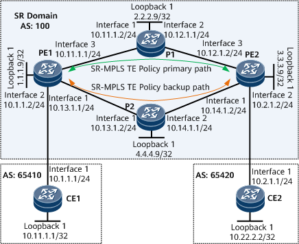
Networking Requirements
CE1 and CE2 belong to a VPN instance named vpna.
The VPN target used by vpna is 111:1.
Configure L3VPN routes to be recursed to SR-MPLS TE Policies to ensure secure communication between users of the same VPN. Because multiple links exist between PEs on the public network, other links must be able to provide protection for the primary link.
Precautions
If an interface connecting a PE to a CE is bound to a VPN instance, Layer 3 configurations, such as the IP address and routing protocol configuration, on the interface will be deleted. Reconfigure them if needed.
Configuration Roadmap
The configuration roadmap is as follows:
Configure IS-IS on the backbone network for the PEs to communicate.
Enable MPLS and SR for each device on the backbone network, and configure static adjacency SIDs.
Configure an SR-MPLS TE Policy with primary and backup paths on each PE.
Configure SBFD and HSB on each PE to enhance SR-MPLS TE Policy reliability.
Apply an import or export route-policy to a specified VPNv4 peer on each PE, and set the Color Extended Community. In this example, an import route-policy with the Color Extended Community is applied.
Establish an MP-IBGP peer relationship between PEs for them to exchange routing information.
Create a VPN instance and enable the IPv4 address family on each PE. Then, bind each PE's interface connecting the PE to a CE to the corresponding VPN instance.
Configure a tunnel selection policy on each PE.
Establish an EBGP peer relationship between each CE-PE pair for the CE and PE to exchange routing information.
Data Preparation
To complete the configuration, you need the following data:
MPLS LSR IDs of PEs and Ps
VPN target and RD of vpna
Procedure
- Configure interface IP addresses for each device on the backbone network.
# Configure PE1.
<HUAWEI> system-view
[~HUAWEI] sysname PE1
[*HUAWEI] commit
[~PE1] interface loopback 1
[*PE1-LoopBack1] ip address 1.1.1.9 32
[*PE1-LoopBack1] quit
[*PE1] interface gigabitethernet0/1/0
[*PE1-GigabitEthernet0/1/0] ip address 10.13.1.1 24
[*PE1-GigabitEthernet0/1/0] quit
[*PE1] interface gigabitethernet0/1/16
[*PE1-GigabitEthernet0/1/16] ip address 10.11.1.1 24
[*PE1-GigabitEthernet0/1/16] quit
[*PE1] commit
# Configure P1.
<HUAWEI> system-view
[~HUAWEI] sysname P1
[*HUAWEI] commit
[~P1] interface loopback 1
[*P1-LoopBack1] ip address 2.2.2.9 32
[*P1-LoopBack1] quit
[*P1] interface gigabitethernet0/1/0
[*P1-GigabitEthernet0/1/0] ip address 10.11.1.2 24
[*P1-GigabitEthernet0/1/0] quit
[*P1] interface gigabitethernet0/1/8
[*P1-GigabitEthernet0/1/8] ip address 10.12.1.1 24
[*P1-GigabitEthernet0/1/8] quit
[*P1] commit
# Configure PE2.
<HUAWEI> system-view
[~HUAWEI] sysname PE2
[*HUAWEI] commit
[~PE2] interface loopback 1
[*PE2-LoopBack1] ip address 3.3.3.9 32
[*PE2-LoopBack1] quit
[*PE2] interface gigabitethernet0/1/0
[*PE2-GigabitEthernet0/1/0] ip address 10.14.1.2 24
[*PE2-GigabitEthernet0/1/0] quit
[*PE2] interface gigabitethernet0/1/16
[*PE2-GigabitEthernet0/1/16] ip address 10.12.1.2 24
[*PE2-GigabitEthernet0/1/16] quit
[*PE2] commit
# Configure P2.
<HUAWEI> system-view
[~HUAWEI] sysname P2
[*HUAWEI] commit
[~P2] interface loopback 1
[*P2-LoopBack1] ip address 4.4.4.9 32
[*P2-LoopBack1] quit
[*P2] interface gigabitethernet0/1/0
[*P2-GigabitEthernet0/1/0] ip address 10.13.1.2 24
[*P2-GigabitEthernet0/1/0] quit
[*P2] interface gigabitethernet0/1/8
[*P2-GigabitEthernet0/1/8] ip address 10.14.1.1 24
[*P2-GigabitEthernet0/1/8] quit
[*P2] commit
- Configure an IGP for each device on the backbone network to implement interworking between PEs and Ps. In this example, the IGP is IS-IS.
# Configure PE1.
[~PE1] isis 1
[*PE1-isis-1] is-level level-1
[*PE1-isis-1] network-entity 10.0000.0000.0001.00
[*PE1-isis-1] quit
[*PE1] interface loopback 1
[*PE1-LoopBack1] isis enable 1
[*PE1-LoopBack1] quit
[*PE1] interface gigabitethernet0/1/0
[*PE1-GigabitEthernet0/1/0] isis enable 1
[*PE1-GigabitEthernet0/1/0] quit
[*PE1] interface gigabitethernet0/1/16
[*PE1-GigabitEthernet0/1/16] isis enable 1
[*PE1-GigabitEthernet0/1/16] quit
[*PE1] commit
# Configure P1.
[~P1] isis 1
[*P1-isis-1] is-level level-1
[*P1-isis-1] network-entity 10.0000.0000.0002.00
[*P1-isis-1] quit
[*P1] interface loopback 1
[*P1-LoopBack1] isis enable 1
[*P1-LoopBack1] quit
[*P1] interface gigabitethernet0/1/0
[*P1-GigabitEthernet0/1/0] isis enable 1
[*P1-GigabitEthernet0/1/0] quit
[*P1] interface gigabitethernet0/1/8
[*P1-GigabitEthernet0/1/8] isis enable 1
[*P1-GigabitEthernet0/1/8] quit
[*P1] commit
# Configure PE2.
[~PE2] isis 1
[*PE2-isis-1] is-level level-1
[*PE2-isis-1] network-entity 10.0000.0000.0003.00
[*PE2-isis-1] quit
[*PE2] interface loopback 1
[*PE2-LoopBack1] isis enable 1
[*PE2-LoopBack1] quit
[*PE2] interface gigabitethernet0/1/16
[*PE2-GigabitEthernet0/1/16] isis enable 1
[*PE2-GigabitEthernet0/1/16] quit
[*PE2] interface gigabitethernet0/1/0
[*PE2-GigabitEthernet0/1/0] isis enable 1
[*PE2-GigabitEthernet0/1/0] quit
[*PE2] commit
# Configure P2.
[~P2] isis 1
[*P2-isis-1] is-level level-1
[*P2-isis-1] network-entity 10.0000.0000.0004.00
[*P2-isis-1] quit
[*P2] interface loopback 1
[*P2-LoopBack1] isis enable 1
[*P2-LoopBack1] quit
[*P2] interface gigabitethernet0/1/0
[*P2-GigabitEthernet0/1/0] isis enable 1
[*P2-GigabitEthernet0/1/0] quit
[*P2] interface gigabitethernet0/1/8
[*P2-GigabitEthernet0/1/8] isis enable 1
[*P2-GigabitEthernet0/1/8] quit
[*P2] commit
- Configure basic MPLS functions for each device on the backbone network.
# Configure PE1.
[~PE1] mpls lsr-id 1.1.1.9
[*PE1] mpls
[*PE1-mpls] commit
[~PE1-mpls] quit
# Configure P1.
[~P1] mpls lsr-id 2.2.2.9
[*P1] mpls
[*P1-mpls] commit
[~P1-mpls] quit
# Configure PE2.
[~PE2] mpls lsr-id 3.3.3.9
[*PE2] mpls
[*PE2-mpls] commit
[~PE2-mpls] quit
# Configure P2.
[~P2] mpls lsr-id 4.4.4.9
[*P2] mpls
[*P2-mpls] commit
[~P2-mpls] quit
- Enable SR for each device on the backbone network.
# Configure PE1.
[~PE1] segment-routing
[*PE1-segment-routing] ipv4 adjacency local-ip-addr 10.11.1.1 remote-ip-addr 10.11.1.2 sid 330000
[*PE1-segment-routing] ipv4 adjacency local-ip-addr 10.13.1.1 remote-ip-addr 10.13.1.2 sid 330001
[*PE1-segment-routing] quit
[*PE1] isis 1
[*PE1-isis-1] cost-style wide
[*PE1-isis-1] segment-routing mpls
[*PE1-isis-1] quit
[*PE1] commit
# Configure P1.
[~P1] segment-routing
[*P1-segment-routing] ipv4 adjacency local-ip-addr 10.11.1.2 remote-ip-addr 10.11.1.1 sid 330003
[*P1-segment-routing] ipv4 adjacency local-ip-addr 10.12.1.1 remote-ip-addr 10.12.1.2 sid 330002
[*P1-segment-routing] quit
[*P1] isis 1
[*P1-isis-1] cost-style wide
[*P1-isis-1] segment-routing mpls
[*P1-isis-1] quit
[*P1] commit
# Configure PE2.
[~PE2] segment-routing
[*PE2-segment-routing] ipv4 adjacency local-ip-addr 10.12.1.2 remote-ip-addr 10.12.1.1 sid 330000
[*PE2-segment-routing] ipv4 adjacency local-ip-addr 10.14.1.2 remote-ip-addr 10.14.1.1 sid 330001
[*PE2-segment-routing] quit
[*PE2] isis 1
[*PE2-isis-1] cost-style wide
[*PE2-isis-1] segment-routing mpls
[*PE2-isis-1] quit
[*PE2] commit
# Configure P2.
[~P2] segment-routing
[*P2-segment-routing] ipv4 adjacency local-ip-addr 10.13.1.2 remote-ip-addr 10.13.1.1 sid 330002
[*P2-segment-routing] ipv4 adjacency local-ip-addr 10.14.1.1 remote-ip-addr 10.14.1.2 sid 330003
[*P2-segment-routing] quit
[*P2] isis 1
[*P2-isis-1] cost-style wide
[*P2-isis-1] segment-routing mpls
[*P2-isis-1] quit
[*P2] commit
- Configure an SR-MPLS TE Policy on each PE.
# Configure PE1.
[~PE1] segment-routing
[~PE1-segment-routing] segment-list pe1
[*PE1-segment-routing-segment-list-pe1] index 10 sid label 330000
[*PE1-segment-routing-segment-list-pe1] index 20 sid label 330002
[*PE1-segment-routing-segment-list-pe1] quit
[*PE1-segment-routing] segment-list pe1backup
[*PE1-segment-routing-segment-list-pe1backup] index 10 sid label 330001
[*PE1-segment-routing-segment-list-pe1backup] index 20 sid label 330003
[*PE1-segment-routing-segment-list-pe1backup] quit
[*PE1-segment-routing] sr-te policy policy100 endpoint 3.3.3.9 color 100
[*PE1-segment-routing-te-policy-policy100] binding-sid 115
[*PE1-segment-routing-te-policy-policy100] mtu 1000
[*PE1-segment-routing-te-policy-policy100] candidate-path preference 100
[*PE1-segment-routing-te-policy-policy100-path] segment-list pe1backup
[*PE1-segment-routing-te-policy-policy100-path] quit
[*PE1-segment-routing-te-policy-policy100] candidate-path preference 200
[*PE1-segment-routing-te-policy-policy100-path] segment-list pe1
[*PE1-segment-routing-te-policy-policy100-path] quit
[*PE1-segment-routing-te-policy-policy100] quit
[*PE1-segment-routing] quit
[*PE1] commit
# Configure PE2.
[~PE2] segment-routing
[~PE2-segment-routing] segment-list pe2
[*PE2-segment-routing-segment-list-pe2] index 10 sid label 330000
[*PE2-segment-routing-segment-list-pe2] index 20 sid label 330003
[*PE2-segment-routing-segment-list-pe2] quit
[*PE2-segment-routing] segment-list pe2backup
[*PE2-segment-routing-segment-list-pe2backup] index 10 sid label 330001
[*PE2-segment-routing-segment-list-pe2backup] index 20 sid label 330002
[*PE2-segment-routing-segment-list-pe2backup] quit
[*PE2-segment-routing] sr-te policy policy200 endpoint 1.1.1.9 color 200
[*PE2-segment-routing-te-policy-policy200] binding-sid 115
[*PE2-segment-routing-te-policy-policy200] mtu 1000
[*PE2-segment-routing-te-policy-policy200] candidate-path preference 100
[*PE2-segment-routing-te-policy-policy200-path] segment-list pe2backup
[*PE2-segment-routing-te-policy-policy200-path] quit
[*PE2-segment-routing-te-policy-policy200] candidate-path preference 200
[*PE2-segment-routing-te-policy-policy200-path] segment-list pe2
[*PE2-segment-routing-te-policy-policy200-path] quit
[*PE2-segment-routing-te-policy-policy200] quit
[*PE2-segment-routing] quit
[*PE2] commit
After completing the configuration, run the display sr-te policy command to check SR-MPLS TE Policy information. The following example uses the command output on PE1.
[~PE1] display sr-te policy
PolicyName : policy100
Endpoint             : 3.3.3.9              Color                : 100
TunnelId             : 1                    TunnelType           : SR-TE Policy
Binding SID          : 115                  MTU                  : 1000
Policy State         : Up                   State Change Time    : 2020-05-18 11:23:39
Admin State          : Up                   Traffic Statistics   : Disable
BFD                  : Disable              Backup Hot-Standby   : Disable
DiffServ-Mode        : -
Candidate-path Count : 2

Candidate-path Preference: 200
Path State           : Active               Path Type            : Primary
Protocol-Origin      : Configuration(30)    Originator           : 0, 0.0.0.0
Discriminator        : 200                  Binding SID          : -
GroupId              : 2                    Policy Name          : policy100
Template ID          : -
Segment-List Count   : 1
 Segment-List        : pe1
  Segment-List ID    : 129                  XcIndex              : 68
  List State         : Up                   BFD State            : -
  EXP                : -                    TTL                  : -
  DeleteTimerRemain  : -                    Weight               : 1
  Label : 330000, 330002

Candidate-path Preference: 100
Path State           : Inactive (Valid)     Path Type            : -
Protocol-Origin      : Configuration(30)    Originator           : 0, 0.0.0.0
Discriminator        : 100                  Binding SID          : -
GroupId              : 1                    Policy Name          : policy100
Template ID          : -
Segment-List Count   : 1
 Segment-List        : pe1backup
  Segment-List ID    : 194                  XcIndex              : -
  List State         : Up                   BFD State            : -
  EXP                : -                    TTL                  : -
  DeleteTimerRemain  : -                    Weight               : 1
  Label : 330001, 330003
- Configure SBFD and HSB on each PE.
# Configure PE1.
[~PE1] bfd
[*PE1-bfd] quit
[*PE1] sbfd
[*PE1-sbfd] reflector discriminator 1.1.1.9
[*PE1-sbfd] quit
[*PE1] segment-routing
[*PE1-segment-routing] sr-te-policy seamless-bfd enable
[*PE1-segment-routing] sr-te-policy backup hot-standby enable
[*PE1-segment-routing] commit
[~PE1-segment-routing] quit
# Configure PE2.
[~PE2] bfd
[*PE2-bfd] quit
[*PE2] sbfd
[*PE2-sbfd] reflector discriminator 3.3.3.9
[*PE2-sbfd] quit
[*PE2] segment-routing
[*PE2-segment-routing] sr-te-policy seamless-bfd enable
[*PE2-segment-routing] sr-te-policy backup hot-standby enable
[*PE2-segment-routing] commit
[~PE2-segment-routing] quit
- Configure a route-policy on each PE.
# Configure PE1.
[~PE1] route-policy color100 permit node 1
[*PE1-route-policy] apply extcommunity color 0:100
[*PE1-route-policy] quit
[*PE1] commit
# Configure PE2.
[~PE2] route-policy color200 permit node 1
[*PE2-route-policy] apply extcommunity color 0:200
[*PE2-route-policy] quit
[*PE2] commit
- Establish an MP-IBGP peer relationship between PEs, apply an import route-policy to a specified VPNv4 peer on each PE, and set the Color Extended Community.
# Configure PE1.
[~PE1] bgp 100
[*PE1-bgp] peer 3.3.3.9 as-number 100
[*PE1-bgp] peer 3.3.3.9 connect-interface loopback 1
[*PE1-bgp] ipv4-family vpnv4
[*PE1-bgp-af-vpnv4] peer 3.3.3.9 enable
[*PE1-bgp-af-vpnv4] peer 3.3.3.9 route-policy color100 import
[*PE1-bgp-af-vpnv4] commit
[~PE1-bgp-af-vpnv4] quit
[~PE1-bgp] quit
# Configure PE2.
[~PE2] bgp 100
[*PE2-bgp] peer 1.1.1.9 as-number 100
[*PE2-bgp] peer 1.1.1.9 connect-interface loopback 1
[*PE2-bgp] ipv4-family vpnv4
[*PE2-bgp-af-vpnv4] peer 1.1.1.9 enable
[*PE2-bgp-af-vpnv4] peer 1.1.1.9 route-policy color200 import
[*PE2-bgp-af-vpnv4] commit
[~PE2-bgp-af-vpnv4] quit
[~PE2-bgp] quit
After completing the configuration, run the display bgp peer or display bgp vpnv4 all peer command on each PE. The following example uses the command output on PE1. The command output shows that a BGP peer relationship has been established between the PEs and is in the Established state.
[~PE1] display bgp peer
 BGP local router ID : 1.1.1.9
 Local AS number : 100
 Total number of peers : 1          Peers in established state : 1
  Peer            V    AS  MsgRcvd  MsgSent     OutQ  Up/Down    State        PrefRcv
  3.3.3.9         4   100        2        6     0     00:00:12   Established   0
[~PE1] display bgp vpnv4 all peer
 BGP local router ID : 1.1.1.9
 Local AS number : 100
 Total number of peers : 1                 Peers in established state : 1
  Peer            V    AS  MsgRcvd  MsgSent    OutQ  Up/Down    State        PrefRcv
  3.3.3.9         4   100   12      18         0     00:09:38   Established   0
- Create a VPN instance and enable the IPv4 address family on each PE. Then, bind each PE's interface connecting the PE to a CE to the corresponding VPN instance.
# Configure PE1.
[~PE1] ip vpn-instance vpna
[*PE1-vpn-instance-vpna] ipv4-family
[*PE1-vpn-instance-vpna-af-ipv4] route-distinguisher 100:1
[*PE1-vpn-instance-vpna-af-ipv4] vpn-target 111:1 both
[*PE1-vpn-instance-vpna-af-ipv4] quit
[*PE1-vpn-instance-vpna] quit
[*PE1] interface gigabitethernet0/1/8
[*PE1-GigabitEthernet0/1/8] ip binding vpn-instance vpna
[*PE1-GigabitEthernet0/1/8] ip address 10.1.1.2 24
[*PE1-GigabitEthernet0/1/8] quit
[*PE1] commit
# Configure PE2.
[~PE2] ip vpn-instance vpna
[*PE2-vpn-instance-vpna] ipv4-family
[*PE2-vpn-instance-vpna-af-ipv4] route-distinguisher 200:1
[*PE2-vpn-instance-vpna-af-ipv4] vpn-target 111:1 both
[*PE2-vpn-instance-vpna-af-ipv4] quit
[*PE2-vpn-instance-vpna] quit
[*PE2] interface gigabitethernet0/1/8
[*PE2-GigabitEthernet0/1/8] ip binding vpn-instance vpna
[*PE2-GigabitEthernet0/1/8] ip address 10.2.1.2 24
[*PE2-GigabitEthernet0/1/8] quit
[*PE2] commit
- Configure a tunnel selection policy on each PE for the specified SR-MPLS TE Policy to be preferentially selected.
# Configure PE1.
[~PE1] tunnel-policy p1
[*PE1-tunnel-policy-p1] tunnel select-seq sr-te-policy load-balance-number 1 unmix
[*PE1-tunnel-policy-p1] quit
[*PE1] ip vpn-instance vpna
[*PE1-vpn-instance-vpna] ipv4-family
[*PE1-vpn-instance-vpna-af-ipv4] tnl-policy p1
[*PE1-vpn-instance-vpna-af-ipv4] quit
[*PE1-vpn-instance-vpna] quit
[*PE1] commit
# Configure PE2.
[~PE2] tunnel-policy p1
[*PE2-tunnel-policy-p1] tunnel select-seq sr-te-policy load-balance-number 1 unmix
[*PE2-tunnel-policy-p1] quit
[*PE2] ip vpn-instance vpna
[*PE2-vpn-instance-vpna] ipv4-family
[*PE2-vpn-instance-vpna-af-ipv4] tnl-policy p1
[*PE2-vpn-instance-vpna-af-ipv4] quit
[*PE2-vpn-instance-vpna] quit
[*PE2] commit
- Establish an EBGP peer relationship between each CE-PE pair.
# Configure CE1.
<HUAWEI> system-view
[~HUAWEI] sysname CE1
[*HUAWEI] commit
[~CE1] interface loopback 1
[*CE1-LoopBack1] ip address 10.11.1.1 32
[*CE1-LoopBack1] quit
[*CE1] interface gigabitethernet0/1/0
[*CE1-GigabitEthernet0/1/0] ip address 10.1.1.1 24
[*CE1-GigabitEthernet0/1/0] quit
[*CE1] bgp 65410
[*CE1-bgp] peer 10.1.1.2 as-number 100
[*CE1-bgp] network 10.11.1.1 32
[*CE1-bgp] quit
[*CE1] commit

The configuration of CE2 is similar to the configuration of CE1. For configuration details, see "Configuration Files" in this section.
After the configuration is complete, run the display ip vpn-instance verbose command on the PEs to check VPN instance configurations. Check that each PE can successfully ping its connected CE.
If a PE has multiple interfaces bound to the same VPN instance, use the -a source-ip-address parameter to specify a source IP address when running the ping -vpn-instance vpn-instance-name -a source-ip-address dest-ip-address command to ping the CE that is connected to the remote PE. If the source IP address is not specified, the ping operation may fail.
# Configure PE1.
[~PE1] bgp 100
[~PE1-bgp] ipv4-family vpn-instance vpna
[*PE1-bgp-vpna] peer 10.1.1.1 as-number 65410
[*PE1-bgp-vpna] commit
[~PE1-bgp-vpna] quit
[~PE1-bgp] quit
The configuration of PE2 is similar to the configuration of PE1. For configuration details, see "Configuration Files" in this section.
After completing the configuration, run the display bgp vpnv4 vpn-instance peer command on each PE. The following example uses the peer relationship between PE1 and CE1. The command output shows that a BGP peer relationship has been established between the PE and CE and is in the Established state.
The following example uses the command output on PE1 to show that a BGP peer relationship has been established between PE1 and CE1.
[~PE1] display bgp vpnv4 vpn-instance vpna peer BGP local router ID : 1.1.1.9 Local AS number : 100 VPN-Instance vpna, Router ID 1.1.1.9: Total number of peers : 1 Peers in established state : 1 Peer V AS MsgRcvd MsgSent OutQ Up/Down State PrefRcv 10.1.1.1 4 65410 91 90 0 01:15:39 Established 1 - Verify the configuration.
After completing the configuration, run the display ip routing-table vpn-instance command on each PE to check information about the loopback interface route toward a CE.
The following example uses the command output on PE1.
[~PE1] display ip routing-table vpn-instance vpna
Route Flags: R - relay, D - download to fib, T - to vpn-instance, B - black hole route
------------------------------------------------------------------------------
Routing Table: vpna
         Destinations : 7        Routes : 7
Destination/Mask    Proto  Pre  Cost     Flags NextHop         Interface
     10.1.1.0/24    Direct 0    0        D     10.1.1.2        GigabitEthernet0/1/8
     10.1.1.2/32    Direct 0    0        D     127.0.0.1       GigabitEthernet0/1/8
   10.1.1.255/32    Direct 0    0        D     127.0.0.1       GigabitEthernet0/1/8
    10.11.1.1/32     EBGP   255  0        RD    10.1.1.1        GigabitEthernet0/1/8
    10.22.2.2/32     IBGP   255  0        RD    3.3.3.9         policy100
      127.0.0.0/8   Direct 0    0        D     127.0.0.1       InLoopBack0
255.255.255.255/32  Direct 0    0        D     127.0.0.1       InLoopBack0
Run the display ip routing-table vpn-instance vpna verbose command on each PE to check details about the loopback interface route toward a CE.
The following example uses the command output on PE1.
[~PE1] display ip routing-table vpn-instance vpna 10.22.2.2 verbose
Route Flags: R - relay, D - download to fib, T - to vpn-instance, B - black hole route
------------------------------------------------------------------------------
Routing Table : vpna
Summary Count : 1

Destination: 10.22.2.2/32
     Protocol: IBGP               Process ID: 0
   Preference: 255                      Cost: 0
      NextHop: 3.3.3.9             Neighbour: 3.3.3.9
        State: Active Adv Relied         Age: 01h18m38s
          Tag: 0                    Priority: low
        Label: 48180                 QoSInfo: 0x0
   IndirectID: 0x10000B9            Instance:
 RelayNextHop: 0.0.0.0             Interface: policy100
     TunnelID: 0x000000003200000041 Flags: RD
The command output shows that the VPN route has been successfully recursed to the specified SR-MPLS TE Policy.
CEs in the same VPN can ping each other. For example, CE1 can ping CE2 at 10.22.2.2.
[~CE1] ping -a 10.11.1.1 10.22.2.2
  PING 10.22.2.2: 56  data bytes, press CTRL_C to break
    Reply from 10.22.2.2: bytes=56 Sequence=1 ttl=251 time=72 ms
    Reply from 10.22.2.2: bytes=56 Sequence=2 ttl=251 time=34 ms
    Reply from 10.22.2.2: bytes=56 Sequence=3 ttl=251 time=50 ms
    Reply from 10.22.2.2: bytes=56 Sequence=4 ttl=251 time=50 ms
    Reply from 10.22.2.2: bytes=56 Sequence=5 ttl=251 time=34 ms
  --- 10.22.2.2 ping statistics ---
    5 packet(s) transmitted
    5 packet(s) received
    0.00% packet loss
    round-trip min/avg/max = 34/48/72 ms
Configuration Files
PE1 configuration file
#
sysname PE1
#
ip vpn-instance vpna
 ipv4-family
  route-distinguisher 100:1
  tnl-policy p1
  vpn-target 111:1 export-extcommunity
  vpn-target 111:1 import-extcommunity
#
bfd
#
sbfd
 reflector discriminator 1.1.1.9
#
mpls lsr-id 1.1.1.9
#
mpls
#
segment-routing
 ipv4 adjacency local-ip-addr 10.11.1.1 remote-ip-addr 10.11.1.2 sid 330000
 ipv4 adjacency local-ip-addr 10.13.1.1 remote-ip-addr 10.13.1.2 sid 330001
 sr-te-policy backup hot-standby enable
 sr-te-policy seamless-bfd enable
 segment-list pe1
  index 10 sid label 330000
  index 20 sid label 330002
 segment-list pe1backup
  index 10 sid label 330001
  index 20 sid label 330003
 sr-te policy policy100 endpoint 3.3.3.9 color 100
  binding-sid 115
  mtu 1000
  candidate-path preference 200
   segment-list pe1
  candidate-path preference 100
   segment-list pe1backup
#
isis 1
 is-level level-1
 cost-style wide
 network-entity 10.0000.0000.0001.00
 segment-routing mpls
#
interface GigabitEthernet0/1/0
 undo shutdown
 ip address 10.13.1.1 255.255.255.0
 isis enable 1
#
interface GigabitEthernet0/1/8
 undo shutdown
 ip binding vpn-instance vpna
 ip address 10.1.1.2 255.255.255.0
#
interface GigabitEthernet0/1/16
 undo shutdown
 ip address 10.11.1.1 255.255.255.0
 isis enable 1
#
interface LoopBack1
 ip address 1.1.1.9 255.255.255.255
 isis enable 1
#
bgp 100
 peer 3.3.3.9 as-number 100
 peer 3.3.3.9 connect-interface LoopBack1
 #
 ipv4-family unicast
  undo synchronization
  peer 3.3.3.9 enable
 #
 ipv4-family vpnv4
  policy vpn-target
  peer 3.3.3.9 enable
  peer 3.3.3.9 route-policy color100 import
 #
 ipv4-family vpn-instance vpna
  peer 10.1.1.1 as-number 65410
#
route-policy color100 permit node 1
 apply extcommunity color 0:100
#
tunnel-policy p1
 tunnel select-seq sr-te-policy load-balance-number 1 unmix
#
return
P1 configuration file
#
sysname P1
#
mpls lsr-id 2.2.2.9
#
mpls
#
segment-routing
 ipv4 adjacency local-ip-addr 10.12.1.1 remote-ip-addr 10.12.1.2 sid 330002
 ipv4 adjacency local-ip-addr 10.11.1.2 remote-ip-addr 10.11.1.1 sid 330003
#
isis 1
 is-level level-1
 cost-style wide
 network-entity 10.0000.0000.0002.00
 segment-routing mpls
#
interface GigabitEthernet0/1/0
 undo shutdown
 ip address 10.11.1.2 255.255.255.0
 isis enable 1
#
interface GigabitEthernet0/1/8
 undo shutdown
 ip address 10.12.1.1 255.255.255.0
 isis enable 1
#
interface LoopBack1
 ip address 2.2.2.9 255.255.255.255
 isis enable 1
#
return
PE2 configuration file
#
sysname PE2
#
ip vpn-instance vpna
 ipv4-family
  route-distinguisher 200:1
  tnl-policy p1
  vpn-target 111:1 export-extcommunity
  vpn-target 111:1 import-extcommunity
#
bfd
#
sbfd
 reflector discriminator 3.3.3.9
#
mpls lsr-id 3.3.3.9
#
mpls
#
segment-routing
 ipv4 adjacency local-ip-addr 10.12.1.2 remote-ip-addr 10.12.1.1 sid 330000
 ipv4 adjacency local-ip-addr 10.14.1.2 remote-ip-addr 10.14.1.1 sid 330001
 sr-te-policy backup hot-standby enable
 sr-te-policy seamless-bfd enable
 segment-list pe2
  index 10 sid label 330000
  index 20 sid label 330003
 segment-list pe2backup
  index 10 sid label 330001
  index 20 sid label 330002
 sr-te policy policy200 endpoint 1.1.1.9 color 200
  binding-sid 115
  mtu 1000
  candidate-path preference 200
   segment-list pe2
  candidate-path preference 100
   segment-list pe2backup
#
isis 1
 is-level level-1
 cost-style wide
 network-entity 10.0000.0000.0003.00
 segment-routing mpls
#
interface GigabitEthernet0/1/0
 undo shutdown
 ip address 10.14.1.2 255.255.255.0
 isis enable 1
#
interface GigabitEthernet0/1/8
 undo shutdown
 ip binding vpn-instance vpna
 ip address 10.2.1.2 255.255.255.0
#
interface GigabitEthernet0/1/16
 undo shutdown
 ip address 10.12.1.2 255.255.255.0
 isis enable 1
#
interface LoopBack1
 ip address 3.3.3.9 255.255.255.255
 isis enable 1
#
bgp 100
 peer 1.1.1.9 as-number 100
 peer 1.1.1.9 connect-interface LoopBack1
 #
 ipv4-family unicast
  undo synchronization
  peer 1.1.1.9 enable
 #
 ipv4-family vpnv4
  policy vpn-target
  peer 1.1.1.9 enable
  peer 1.1.1.9 route-policy color200 import
 #
 ipv4-family vpn-instance vpna
  peer 10.2.1.1 as-number 65420
#
route-policy color200 permit node 1
 apply extcommunity color 0:200
#
tunnel-policy p1
 tunnel select-seq sr-te-policy load-balance-number 1 unmix
#
return
P2 configuration file
#
sysname P2
#
mpls lsr-id 4.4.4.9
#
mpls
#
segment-routing
 ipv4 adjacency local-ip-addr 10.13.1.2 remote-ip-addr 10.13.1.1 sid 330002
 ipv4 adjacency local-ip-addr 10.14.1.1 remote-ip-addr 10.14.1.2 sid 330003
#
isis 1
 is-level level-1
 cost-style wide
 network-entity 10.0000.0000.0004.00
 segment-routing mpls
#
interface GigabitEthernet0/1/0
 undo shutdown
 ip address 10.13.1.2 255.255.255.0
 isis enable 1
#
interface GigabitEthernet0/1/8
 undo shutdown
 ip address 10.14.1.1 255.255.255.0
 isis enable 1
#
interface LoopBack1
 ip address 4.4.4.9 255.255.255.255
 isis enable 1
#
return
CE1 configuration file
#
sysname CE1
#
interface GigabitEthernet0/1/0
 undo shutdown
 ip address 10.1.1.1 255.255.255.0
#
interface LoopBack1
 ip address 10.11.1.1 255.255.255.255
#
bgp 65410
 peer 10.1.1.2 as-number 100
 #
 ipv4-family unicast
  network 10.11.1.1 255.255.255.255
  peer 10.1.1.2 enable
#
return
CE2 configuration file
#
sysname CE2
#
interface GigabitEthernet0/1/0
 undo shutdown
 ip address 10.2.1.1 255.255.255.0
#
interface LoopBack1
 ip address 10.22.2.2 255.255.255.255
#
bgp 65420
 peer 10.2.1.2 as-number 100
 #
 ipv4-family unicast
  network 10.22.2.2 255.255.255.255
  peer 10.2.1.2 enable
#
return