Example for Redirecting Public IPv4 BGP FlowSpec Routes to SR-MPLS TE Policies
This section provides an example for redirecting public IPv4 BGP FlowSpec routes to SR-MPLS TE Policies to meet the steering requirements of different services.
Networking Requirements
In traditional BGP FlowSpec-based traffic optimization, traffic transmitted over paths with the same source and destination nodes can be redirected to only one path, which does not achieve accurate traffic steering. With the function to redirect a public IPv4 BGP FlowSpec route to an SR-MPLS TE Policy, a device can redirect traffic transmitted over paths with the same source and destination nodes to different SR-MPLS TE Policies.
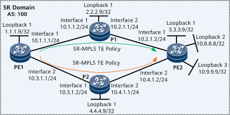
On the network shown in Figure 1, there are two SR-MPLS TE Policies in the direction from PE1 to PE2. PE2 is connected to two local networks (10.8.8.8/32 and 10.9.9.9/32). It is required that traffic destined for different networks be redirected to different SR-MPLS TE Policies.

Configuration Roadmap
The configuration roadmap is as follows:
Configure IS-IS on the backbone network for the PEs to communicate.
Enable MPLS on the backbone network and configure SR and static adjacency labels.
Configure two SR-MPLS TE Policies from PE1 to PE2.
- Configure static FlowSpec routes on PE1 and redirect the routes to the SR-MPLS TE Policies.
- Configure a tunnel policy.
Establish a BGP FlowSpec peer relationship between the PEs.
Data Preparation
To complete the configuration, you need the following data:
MPLS LSR IDs on the PEs and Ps
Adjacency labels on the PEs and Ps
Procedure
- Configure interface IP addresses.
# Configure PE1.
<HUAWEI> system-view
[~HUAWEI] sysname PE1
[*HUAWEI] commit
[~PE1] interface loopback 1
[*PE1-LoopBack1] ip address 1.1.1.9 32
[*PE1-LoopBack1] quit
[*PE1] interface gigabitethernet0/1/0
[*PE1-GigabitEthernet0/1/0] ip address 10.1.1.1 24
[*PE1-GigabitEthernet0/1/0] quit
[*PE1] interface gigabitethernet0/1/8
[*PE1-GigabitEthernet0/1/8] ip address 10.3.1.1 24
[*PE1-GigabitEthernet0/1/8] quit
[*PE1] commit
# Configure P1.
<HUAWEI> system-view
[~HUAWEI] sysname P1
[*HUAWEI] commit
[~P1] interface loopback 1
[*P1-LoopBack1] ip address 2.2.2.9 32
[*P1-LoopBack1] quit
[*P1] interface gigabitethernet0/1/0
[*P1-GigabitEthernet0/1/0] ip address 10.1.1.2 24
[*P1-GigabitEthernet0/1/0] quit
[*P1] interface gigabitethernet0/1/8
[*P1-GigabitEthernet0/1/8] ip address 10.2.1.1 24
[*P1-GigabitEthernet0/1/8] quit
[*P1] commit
# Configure PE2.
<HUAWEI> system-view
[~HUAWEI] sysname PE2
[*HUAWEI] commit
[~PE2] interface loopback 1
[*PE2-LoopBack1] ip address 3.3.3.9 32
[*PE2-LoopBack1] quit
[*PE2] interface gigabitethernet0/1/0
[*PE2-GigabitEthernet0/1/0] ip address 10.2.1.2 24
[*PE2-GigabitEthernet0/1/0] quit
[*PE2] interface gigabitethernet0/1/8
[*PE2-GigabitEthernet0/1/8] ip address 10.4.1.2 24
[*PE2-GigabitEthernet0/1/8] quit
[*PE2] commit
# Configure P2.
<HUAWEI> system-view
[~HUAWEI] sysname P2
[*HUAWEI] commit
[~P2] interface loopback 1
[*P2-LoopBack1] ip address 4.4.4.9 32
[*P2-LoopBack1] quit
[*P2] interface gigabitethernet0/1/0
[*P2-GigabitEthernet0/1/0] ip address 10.3.1.2 24
[*P2-GigabitEthernet0/1/0] quit
[*P2] interface gigabitethernet0/1/8
[*P2-GigabitEthernet0/1/8] ip address 10.4.1.1 24
[*P2-GigabitEthernet0/1/8] quit
[*P2] commit
- Configure an IGP on the backbone network for the PEs and Ps to communicate. The following example uses IS-IS.
# Configure PE1.
[~PE1] isis 1
[*PE1-isis-1] is-level level-1
[*PE1-isis-1] network-entity 10.0000.0000.0001.00
[*PE1-isis-1] quit
[*PE1] interface loopback 1
[*PE1-LoopBack1] isis enable 1
[*PE1-LoopBack1] quit
[*PE1] interface gigabitethernet0/1/0
[*PE1-GigabitEthernet0/1/0] isis enable 1
[*PE1-GigabitEthernet0/1/0] quit
[*PE1] interface gigabitethernet0/1/8
[*PE1-GigabitEthernet0/1/8] isis enable 1
[*PE1-GigabitEthernet0/1/8] quit
[*PE1] commit
# Configure P1.
[~P1] isis 1
[*P1-isis-1] is-level level-1
[*P1-isis-1] network-entity 10.0000.0000.0002.00
[*P1-isis-1] quit
[*P1] interface loopback 1
[*P1-LoopBack1] isis enable 1
[*P1-LoopBack1] quit
[*P1] interface gigabitethernet0/1/0
[*P1-GigabitEthernet0/1/0] isis enable 1
[*P1-GigabitEthernet0/1/0] quit
[*P1] interface gigabitethernet0/1/8
[*P1-GigabitEthernet0/1/8] isis enable 1
[*P1-GigabitEthernet0/1/8] quit
[*P1] commit
# Configure PE2.
[~PE2] isis 1
[*PE2-isis-1] is-level level-1
[*PE2-isis-1] network-entity 10.0000.0000.0003.00
[*PE2-isis-1] quit
[*PE2] interface loopback 1
[*PE2-LoopBack1] isis enable 1
[*PE2-LoopBack1] quit
[*PE2] interface gigabitethernet0/1/0
[*PE2-GigabitEthernet0/1/0] isis enable 1
[*PE2-GigabitEthernet0/1/0] quit
[*PE2] interface gigabitethernet0/1/8
[*PE2-GigabitEthernet0/1/8] isis enable 1
[*PE2-GigabitEthernet0/1/8] quit
[*PE2] commit
# Configure P2.
[~P2] isis 1
[*P2-isis-1] is-level level-1
[*P2-isis-1] network-entity 10.0000.0000.0004.00
[*P2-isis-1] quit
[*P2] interface loopback 1
[*P2-LoopBack1] isis enable 1
[*P2-LoopBack1] quit
[*P2] interface gigabitethernet0/1/0
[*P2-GigabitEthernet0/1/0] isis enable 1
[*P2-GigabitEthernet0/1/0] quit
[*P2] interface gigabitethernet0/1/8
[*P2-GigabitEthernet0/1/8] isis enable 1
[*P2-GigabitEthernet0/1/8] quit
[*P2] commit
- Configure basic MPLS functions on the backbone network.
# Configure PE1.
[~PE1] mpls lsr-id 1.1.1.9
[*PE1] mpls
[*PE1-mpls] commit
[~PE1-mpls] quit
# Configure P1.
[~P1] mpls lsr-id 2.2.2.9
[*P1] mpls
[*P1-mpls] commit
[~P1-mpls] quit
# Configure PE2.
[~PE2] mpls lsr-id 3.3.3.9
[*PE2] mpls
[*PE2-mpls] commit
[~PE2-mpls] quit
# Configure P2.
[~P2] mpls lsr-id 4.4.4.9
[*P2] mpls
[*P2-mpls] commit
[~P2-mpls] quit
- Configure SR on the backbone network.
# Configure PE1.
[~PE1] segment-routing
[*PE1-segment-routing] ipv4 adjacency local-ip-addr 10.1.1.1 remote-ip-addr 10.1.1.2 sid 330000
[*PE1-segment-routing] ipv4 adjacency local-ip-addr 10.3.1.1 remote-ip-addr 10.3.1.2 sid 330001
[*PE1-segment-routing] quit
[*PE1] isis 1
[*PE1-isis-1] cost-style wide
[*PE1-isis-1] segment-routing mpls
[*PE1-isis-1] quit
[*PE1] commit
# Configure P1.
[~P1] segment-routing
[*P1-segment-routing] ipv4 adjacency local-ip-addr 10.1.1.2 remote-ip-addr 10.1.1.1 sid 330003
[*P1-segment-routing] ipv4 adjacency local-ip-addr 10.2.1.1 remote-ip-addr 10.2.1.2 sid 330002
[*P1-segment-routing] quit
[*P1] isis 1
[*P1-isis-1] cost-style wide
[*P1-isis-1] segment-routing mpls
[*P1-isis-1] quit
[*P1] commit
# Configure PE2.
[~PE2] segment-routing
[*PE2-segment-routing] ipv4 adjacency local-ip-addr 10.2.1.2 remote-ip-addr 10.2.1.1 sid 330000
[*PE2-segment-routing] ipv4 adjacency local-ip-addr 10.4.1.2 remote-ip-addr 10.4.1.1 sid 330001
[*PE2-segment-routing] quit
[*PE2] isis 1
[*PE2-isis-1] cost-style wide
[*PE2-isis-1] segment-routing mpls
[*PE2-isis-1] quit
[*PE2] commit
# Configure P2.
[~P2] segment-routing
[*P2-segment-routing] ipv4 adjacency local-ip-addr 10.3.1.2 remote-ip-addr 10.3.1.1 sid 330002
[*P2-segment-routing] ipv4 adjacency local-ip-addr 10.4.1.1 remote-ip-addr 10.4.1.2 sid 330003
[*P2-segment-routing] quit
[*P2] isis 1
[*P2-isis-1] cost-style wide
[*P2-isis-1] segment-routing mpls
[*P2-isis-1] quit
[*P2] commit
- Configure SR-MPLS TE Policies.
# Configure PE1.
[~PE1] segment-routing
[~PE1-segment-routing] segment-list pe1
[*PE1-segment-routing-segment-list-pe1] index 10 sid label 330000
[*PE1-segment-routing-segment-list-pe1] index 20 sid label 330002
[*PE1-segment-routing-segment-list-pe1] quit
[*PE1-segment-routing] segment-list pe1backup
[*PE1-segment-routing-segment-list-pe1backup] index 10 sid label 330001
[*PE1-segment-routing-segment-list-pe1backup] index 20 sid label 330003
[*PE1-segment-routing-segment-list-pe1backup] quit
[*PE1-segment-routing] sr-te policy policy100 endpoint 3.3.3.9 color 100
[*PE1-segment-routing-te-policy-policy100] binding-sid 115
[*PE1-segment-routing-te-policy-policy100] mtu 1000
[*PE1-segment-routing-te-policy-policy100] candidate-path preference 200
[*PE1-segment-routing-te-policy-policy100-path] segment-list pe1
[*PE1-segment-routing-te-policy-policy100-path] quit
[*PE1-segment-routing-te-policy-policy100] quit
[*PE1-segment-routing] sr-te policy policy200 endpoint 3.3.3.9 color 200
[*PE1-segment-routing-te-policy-policy200] binding-sid 125
[*PE1-segment-routing-te-policy-policy200] mtu 1000
[*PE1-segment-routing-te-policy-policy200] candidate-path preference 200
[*PE1-segment-routing-te-policy-policy200-path] segment-list pe1backup
[*PE1-segment-routing-te-policy-policy200-path] quit
[*PE1-segment-routing-te-policy-policy200] quit
[*PE1-segment-routing] quit
[*PE1] commit
After the configuration is complete, you can run the display sr-te policy command to check SR-MPLS TE Policy information.
[~PE1] display sr-te policy
PolicyName : policy100
Endpoint             : 3.3.3.9              Color                : 100
TunnelId             : 8193                 TunnelType           : SR-TE Policy
Binding SID          : 115                  MTU                  : 1000
Policy State         : Up                   State Change Time    : 2020-05-16 10:18:16
Admin State          : UP                   Traffic Statistics   : Disable
BFD                  : Disable              Backup Hot-Standby   : Disable
DiffServ-Mode        : -
Candidate-path Count : 1

Candidate-path Preference: 200
Path State           : Active               Path Type            : Primary
Protocol-Origin      : Configuration(30)    Originator           : 0, 0.0.0.0
Discriminator        : 200                  Binding SID          : 115
GroupId              : 8193                 Policy Name          : policy100
Template ID          : -
Segment-List Count   : 1
 Segment-List        : pe1
  Segment-List ID    : 32771                XcIndex              : 2032771
  List State         : Up                   BFD State            : -
  EXP                : -                    TTL                  : -
  DeleteTimerRemain  : -                    Weight               : 1
  Label : 330000, 330002

PolicyName : policy200
Endpoint             : 3.3.3.9              Color                : 200
TunnelId             : 8194                 TunnelType           : SR-TE Policy
Binding SID          : 125                  MTU                  : 1000
Policy State         : Up                   State Change Time    : 2020-05-16 10:20:32
Admin State          : Up                   Traffic Statistics   : Disable
BFD                  : Disable              Backup Hot-Standby   : Disable
DiffServ-Mode        : -
Candidate-path Count : 1

Candidate-path Preference: 200
Path State           : Active               Path Type            : Primary
Protocol-Origin      : Configuration(30)    Originator           : 0, 0.0.0.0
Discriminator        : 200                  Binding SID          : 125
GroupId              : 8194                 Policy Name          : policy200
Template ID          : -
Segment-List Count   : 1
 Segment-List        : pe1backup
  Segment-List ID    : 32833                XcIndex              : 2032833
  List State         : Up                   BFD State            : -
  EXP                : -                    TTL                  : -
  DeleteTimerRemain  : -                    Weight               : 1
  Label : 330001, 330003
- Establish a BGP peer relationship between the PEs and import local network routes to PE2.
In this example, loopback addresses 10.8.8.8/32 and 10.9.9.9/32 are used to simulate two local networks on PE2.
# Configure PE1.
[~PE1] bgp 100
[*PE1-bgp] peer 3.3.3.9 as-number 100
[*PE1-bgp] peer 3.3.3.9 connect-interface loopback 1
[*PE1-bgp] commit
[~PE1-bgp] quit
# Configure PE2.
[~PE2] interface loopback 2
[*PE2-LoopBack2] ip address 10.8.8.8 32
[*PE2-LoopBack2] quit
[*PE2] interface loopback 3
[*PE2-LoopBack3] ip address 10.9.9.9 32
[*PE2-LoopBack3] quit
[*PE2] bgp 100
[*PE2-bgp] peer 1.1.1.9 as-number 100
[*PE2-bgp] peer 1.1.1.9 connect-interface loopback 1
[*PE2-bgp] network 10.8.8.8 32
[*PE2-bgp] network 10.9.9.9 32
[*PE2-bgp] commit
[~PE2-bgp] quit
After the configuration is complete, run the display bgp peer command on the PEs and check whether a BGP peer relationship has been established between the PEs. If the Established state is displayed in the command output, the BGP peer relationship has been established successfully. The following example uses the command output on PE1.
[~PE1] display bgp peer BGP local router ID : 1.1.1.9 Local AS number : 100 Total number of peers : 1 Peers in established state : 1 Peer V AS MsgRcvd MsgSent OutQ Up/Down State PrefRcv 3.3.3.9 4 100 201 202 0 02:51:56 Established 2 - Establish a BGP FlowSpec peer relationship between the PEs.
# Configure PE1.
[~PE1] bgp 100
[~PE1-bgp] ipv4-family flow
[*PE1-bgp-af-ipv4-flow] peer 3.3.3.9 enable
[*PE1-bgp-af-ipv4-flow] commit
[~PE1-bgp-af-ipv4-flow] quit
[~PE1-bgp] quit
# Configure PE2.
[~PE2] bgp 100
[~PE2-bgp] ipv4-family flow
[*PE2-bgp-af-ipv4-flow] peer 1.1.1.9 enable
[*PE2-bgp-af-ipv4-flow] commit
[~PE2-bgp-af-ipv4-flow] quit
[~PE2-bgp] quit
After the configuration is complete, run the display bgp flow peer command on the PEs and check whether a BGP FlowSpec peer relationship has been established between the PEs. If the Established state is displayed in the command output, the BGP FlowSpec peer relationship has been established successfully. The following example uses the command output on PE1.
[~PE1] display bgp flow peer

 BGP local router ID : 1.1.1.9
 Local AS number : 100
 Total number of peers : 1                 Peers in established state : 1

  Peer            V          AS  MsgRcvd  MsgSent  OutQ  Up/Down       State  PrefRcv
  3.3.3.9         4         100      208      209     0 02:58:16 Established        0
- Configure static BGP FlowSpec route redirection on PE1.
BGP FlowSpec route redirection is based on <Redirection IP address, Color>. If the redirection IP address and color attributes of a BGP FlowSpec route match the endpoint and color attributes of an SR-MPLS TE Policy, the route can be successfully redirected to the SR-MPLS TE Policy.
In this example, the traffic destined for 10.8.8.8/32 needs to be redirected to the SR-MPLS TE Policy named policy100, and the traffic destined for 10.9.9.9/32 needs to be redirected to the SR-MPLS TE Policy named policy200.
# Configure PE1.
[~PE1] flow-route PE1toPE2
[*PE1-flow-route] if-match destination 10.8.8.8 255.255.255.255
[*PE1-flow-route] apply redirect ip 3.3.3.9:0 color 0:100
[*PE1-flow-route] quit
[*PE1] flow-route PE1toPE2b
[*PE1-flow-route] if-match destination 10.9.9.9 255.255.255.255
[*PE1-flow-route] apply redirect ip 3.3.3.9:0 color 0:200
[*PE1-flow-route] commit
[~PE1-flow-route] quit
- Configure a tunnel policy on each PE to preferentially select an SR-MPLS TE Policy.
# Configure PE1.
[~PE1] tunnel-policy p1
[*PE1-tunnel-policy-p1] tunnel select-seq sr-te-policy load-balance-number 1 unmix
[*PE1-tunnel-policy-p1] quit
[*PE1] tunnel-selector p1 permit node 1
[*PE1-tunnel-selector] apply tunnel-policy p1
[*PE1-tunnel-selector] quit
[*PE1] bgp 100
[*PE1-bgp] ipv4-family flow
[*PE1-bgp-af-ipv4-flow] redirect ip recursive-lookup tunnel tunnel-selector p1
[*PE1-bgp-af-ipv4-flow] commit
[~PE1-bgp-af-ipv4-flow] quit
[~PE1-bgp] quit
- Verify the configuration.
# Display BGP FlowSpec route information on PE1.
[~PE1] display bgp flow routing-table
 BGP Local router ID is 1.1.1.9
 Status codes: * - valid, > - best, d - damped, x - best external, a - add path,
               h - history,  i - internal, s - suppressed, S - Stale
               Origin : i - IGP, e - EGP, ? - incomplete
 RPKI validation codes: V - valid, I - invalid, N - not-found


 Total Number of Routes: 2
 * >  ReIndex : 24577
      Dissemination Rules:
       Destination IP : 10.8.8.8/32
       MED      : 0                   PrefVal  : 0
       LocalPref:
       Path/Ogn :  i
 * >  ReIndex : 24578
      Dissemination Rules:
       Destination IP : 10.9.9.9/32
       MED      : 0                   PrefVal  : 0
       LocalPref:
       Path/Ogn :  i
# Display the traffic redirection information carried in a single BGP FlowSpec route based on the ReIndex value shown in the preceding command output.
[~PE1] display bgp flow routing-table 24577
 BGP local router ID : 1.1.1.9
 Local AS number : 100
 ReIndex : 24577
 Dissemination Rules :
   Destination IP : 10.8.8.8/32

 BGP flow-ipv4 routing table entry information of 24577:
 Local : PE1toPE2
 Match action :
   apply redirect ip 3.3.3.9:0 color 0:100
 Route Duration: 0d03h10m19s
 AS-path Nil, origin igp, MED 0, pref-val 0, valid, local, best, pre 255
 Advertised to such 1 peers:
    3.3.3.9
[~PE1] display bgp flow routing-table 24578
 BGP local router ID : 1.1.1.9
 Local AS number : 100
 ReIndex : 24578
 Dissemination Rules :
   Destination IP : 10.9.9.9/32

 BGP flow-ipv4 routing table entry information of 24578:
 Local : PE1toPE2b
 Match action :
   apply redirect ip 3.3.3.9:0 color 0:200
 Route Duration: 0d03h11m39s
 AS-path Nil, origin igp, MED 0, pref-val 0, valid, local, best, pre 255
 Advertised to such 1 peers:
    3.3.3.9
# Inject test traffic to PE1 and enable SR-MPLS TE Policy traffic statistics collection. Then, run the display sr-te policy traffic-statistics [ endpoint ipv4-address color color-value | policy-name name-value | binding-sid binding-sid ] command to check SR-MPLS TE Policy traffic statistics.
Configuration Files
PE1 configuration file
#
sysname PE1
#
mpls lsr-id 1.1.1.9
#
mpls
#
segment-routing
 ipv4 adjacency local-ip-addr 10.1.1.1 remote-ip-addr 10.1.1.2 sid 330000
 ipv4 adjacency local-ip-addr 10.3.1.1 remote-ip-addr 10.3.1.2 sid 330001
 segment-list pe1
  index 10 sid label 330000
  index 20 sid label 330002
 segment-list pe1backup
  index 10 sid label 330001
  index 20 sid label 330003
 sr-te policy policy100 endpoint 3.3.3.9 color 100
  binding-sid 115
  mtu 1000
  candidate-path preference 200
   segment-list pe1
 sr-te policy policy200 endpoint 3.3.3.9 color 200
  binding-sid 125
  mtu 1000
  candidate-path preference 200
   segment-list pe1backup
#
isis 1
 is-level level-1
 cost-style wide
 network-entity 10.0000.0000.0001.00
 segment-routing mpls
#
interface GigabitEthernet0/1/0
 undo shutdown
 ip address 10.1.1.1 255.255.255.0
 isis enable 1
#
interface GigabitEthernet0/1/8
 undo shutdown
 ip address 10.3.1.1 255.255.255.0
 isis enable 1
#
interface LoopBack1
 ip address 1.1.1.9 255.255.255.255
 isis enable 1
#
bgp 100
 peer 3.3.3.9 as-number 100
 peer 3.3.3.9 connect-interface LoopBack1
 #
 ipv4-family unicast
  undo synchronization
  peer 3.3.3.9 enable
 #
 ipv4-family flow
  peer 3.3.3.9 enable
  redirect ip recursive-lookup tunnel tunnel-selector p1
#
flow-route PE1toPE2
 if-match destination 10.8.8.8 255.255.255.255
 apply redirect ip 3.3.3.9:0 color 0:100
#
flow-route PE1toPE2b
 if-match destination 10.9.9.9 255.255.255.255
 apply redirect ip 3.3.3.9:0 color 0:200
#
tunnel-policy p1
 tunnel select-seq sr-te-policy load-balance-number 1 unmix
#
tunnel-selector p1 permit node 1
 apply tunnel-policy p1
#
return
P1 configuration file
#
sysname P1
#
mpls lsr-id 2.2.2.9
#
mpls
#
segment-routing
 ipv4 adjacency local-ip-addr 10.2.1.1 remote-ip-addr 10.2.1.2 sid 330002
 ipv4 adjacency local-ip-addr 10.1.1.2 remote-ip-addr 10.1.1.1 sid 330003
#
isis 1
 is-level level-1
 cost-style wide
 network-entity 10.0000.0000.0002.00
 segment-routing mpls
#
interface GigabitEthernet0/1/0
 undo shutdown
 ip address 10.1.1.2 255.255.255.0
 isis enable 1
#
interface GigabitEthernet0/1/8
 undo shutdown
 ip address 10.2.1.1 255.255.255.0
 isis enable 1
#
interface LoopBack1
 ip address 2.2.2.9 255.255.255.255
 isis enable 1
#
return
PE2 configuration file
#
sysname PE2
#
mpls lsr-id 3.3.3.9
#
mpls
#
segment-routing
 ipv4 adjacency local-ip-addr 10.2.1.2 remote-ip-addr 10.2.1.1 sid 330000
 ipv4 adjacency local-ip-addr 10.4.1.2 remote-ip-addr 10.4.1.1 sid 330001
#
isis 1
 is-level level-1
 cost-style wide
 network-entity 10.0000.0000.0003.00
 segment-routing mpls
#
interface GigabitEthernet0/1/0
 undo shutdown
 ip address 10.2.1.2 255.255.255.0
 isis enable 1
#
interface GigabitEthernet0/1/8
 undo shutdown
 ip address 10.4.1.2 255.255.255.0
 isis enable 1
#
interface LoopBack1
 ip address 3.3.3.9 255.255.255.255
 isis enable 1
#
interface LoopBack2
 ip address 10.8.8.8 255.255.255.255
#
interface LoopBack3
 ip address 10.9.9.9 255.255.255.255
#
bgp 100
 peer 1.1.1.9 as-number 100
 peer 1.1.1.9 connect-interface LoopBack1
 #
 ipv4-family unicast
  undo synchronization
  network 10.8.8.8 255.255.255.255
  network 10.9.9.9 255.255.255.255
  peer 1.1.1.9 enable
 #
 ipv4-family flow
  peer 1.1.1.9 enable
#
return
P2 configuration file
#
sysname P2
#
mpls lsr-id 4.4.4.9
#
mpls
#
segment-routing
 ipv4 adjacency local-ip-addr 10.3.1.2 remote-ip-addr 10.3.1.1 sid 330002
 ipv4 adjacency local-ip-addr 10.4.1.1 remote-ip-addr 10.4.1.2 sid 330003
#
isis 1
 is-level level-1
 cost-style wide
 network-entity 10.0000.0000.0004.00
 segment-routing mpls
#
interface GigabitEthernet0/1/0
 undo shutdown
 ip address 10.3.1.2 255.255.255.0
 isis enable 1
#
interface GigabitEthernet0/1/8
 undo shutdown
 ip address 10.4.1.1 255.255.255.0
 isis enable 1
#
interface LoopBack1
 ip address 4.4.4.9 255.255.255.255
 isis enable 1
#
return