Segment Routing MPLS Fundamentals
Basic Concepts
Segment Routing (SR) domain: a set of SR nodes.
Segment ID (SID): unique identifier of a segment. A SID can be mapped to an MPLS label in the forwarding plane.
Segment Routing global block (SRGB): a set of user-specified global labels reserved for SR-MPLS.
- Segment Routing local block (SRLB): a set of user-specified local labels reserved for Segment Routing MPLS. These labels are configured and effective only on the local device. However, they are advertised through an IGP. Therefore, they are globally visible. The SRLB is mainly used for binding SIDs.
Segment Classification
Category |
Generation Mode |
Function |
|---|---|---|
Prefix segment |
Manually configured |
Identifies the prefix of a destination address. Prefix segments are propagated to other devices through an IGP. They are visible to and effective on all the devices. Each prefix segment is identified by a prefix segment ID (SID), which is an offset value within the SRGB range advertised by the ingress. The receive end uses its local SRGB to compute label values for generating MPLS forwarding entries. |
Adjacency segment |
Dynamically allocated by the ingress through a protocol or manually configured |
Identifies an adjacency on a network. Adjacency segments are propagated to other devices through an IGP. They are visible to all the devices but effective only on the local device. Each adjacency segment is identified by an adjacency SID, which is a local SID out of the SRGB range. |
Node segment |
Manually configured |
Identifies a specific node. Node segments are special prefix segments. When an IP address is configured as a prefix for a loopback interface of a node, the prefix SID of the node is the node SID. |
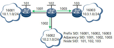
In general, a prefix SID identifies a destination address, and an adjacency SID identifies a link for outgoing data packets. The prefix and adjacency SIDs are similar to the destination IP address and outbound interface in conventional IP forwarding, respectively. In an IGP area, devices propagate their node and adjacency SIDs using extended IGP messages, so that any device in the area can obtain information about the other devices.
Combining prefix (node) and adjacency SIDs in sequence can construct any network path. Every hop on a path identifies the next hop based on the top SID in the label stack. SID information is stacked in sequence at the top of the data header. If the top SID identifies another node, the receive node forwards the data packet to that node in ECMP mode. If the top SID identifies the local node, the receive node removes the top SID and proceeds with the follow-up procedure.
Prefix, adjacency, and node SIDs can either be used separately or be combined. They are mainly used in the following three modes:
Prefix SID
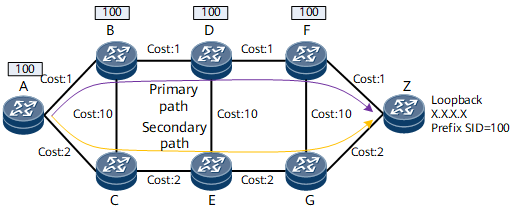
If equal-cost paths exist on the network, ECMP can be implemented. If no equal-cost paths exist, link backup can be implemented. Therefore, prefix SID-based forwarding paths are not fixed, and the ingress cannot control the entire packet forwarding path.
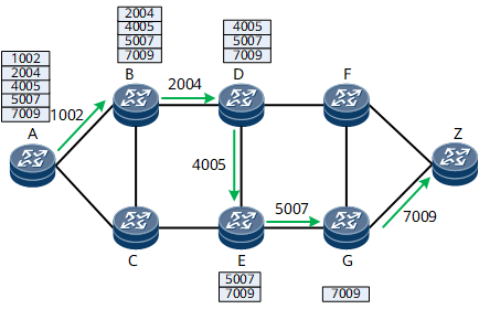
Adjacency SID
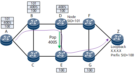
Adjacency SID + Node SID
SR Forwarding Mechanism
SR can be directly used in the MPLS architecture, without requiring any changes to the forwarding plane. SIDs are encoded as MPLS labels, and the segment list is encoded as a label stack. The segment to be processed is at the stack top. Once a segment is processed, the corresponding label is removed from the label stack.
SR based on the MPLS forwarding mechanism is also called SR-MPLS.
SR Label Conflicts and Handling Rules
Prefix SIDs are manually configured on different devices, which may result in label conflicts. Label conflicts are classified as prefix conflicts or SID conflicts. A prefix conflict indicates that the same prefix is associated with different SIDs, whereas a SID conflict indicates that the same SID is associated with different prefixes.
- The route with the largest prefix mask is preferred.
- The route with the smallest prefix is preferred.
- The route with the smallest SID is preferred.
- a. 1.1.1.1/32 1
- b. 1.1.1.1/32 2
- c. 2.2.2.2/32 3
- d. 3.3.3.3/32 1
- Prefix conflicts are handled first. Routes a and b encounter a prefix conflict. Route a has a smaller SID than route b. Therefore, route a is preferred. After route b is excluded, the following three routes are left:
- a. 1.1.1.1/32 1
- c. 2.2.2.2/32 3
- d. 3.3.3.3/32 1
- SID conflicts are then handled. Routes a and d encounter a SID conflict. Route a has a smaller prefix than route d. Therefore, route a is preferred. After route d is excluded, the following two routes are left:
- a. 1.1.1.1/32 1
- c. 2.2.2.2/32 3