TI-LFA FRR
Topology-independent loop-free alternate (TI-LFA) fast reroute (FRR) provides link and node protection for Segment Routing (SR) tunnels. If a link or node fails, it enables traffic to be rapidly switched to a backup path, minimizing traffic loss.
SR-MPLS TI-LFA FRR applies to both SR-MPLS BE and loose SR-MPLS TE scenarios.
Related Concepts
Concept |
Definition |
|---|---|
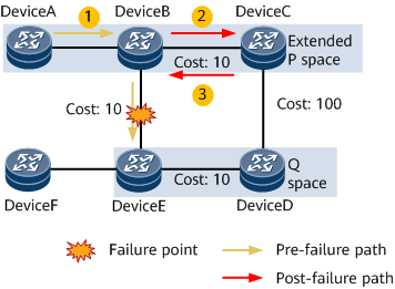
P space |
The P space is a set of nodes reachable from the source node of a protected link using the shortest path tree (SPT) rooted at the source node without traversing the protected link. |
Extended P space |
The extended P space is a set of nodes reachable from all the neighbors of a protected link's source node using SPTs rooted at the neighbors without traversing the protected link. A node in the P space or extended P space is called a P node. |
Q space |
The Q space is a set of nodes reachable from the destination node of a protected link using the reverse SPT rooted at the destination node without traversing the protected link. A node in the Q space is called a Q node. |
PQ node |
A PQ node resides in both the (extended) P space and Q space and functions as the destination node of a protected tunnel. |
LFA |
With LFA, a device runs the SPF algorithm to compute the shortest paths to the destination, using each neighbor that can provide a backup link as a root node. The device then computes a group of loop-free backup links with the minimum cost. For more information about LFA, see IS-IS Auto FRR. |
RLFA |
Remote LFA (RLFA) computes a PQ node based on a protected link and establishes a tunnel between the source and PQ nodes to offer alternate next hop protection. If the protected link fails, traffic is automatically switched to the backup path, improving network reliability. For more information about RLFA, see IS-IS Auto FRR. NOTE:
When computing an RLFA FRR backup path, Huawei devices compute the extended P space by default. |
TI-LFA |
In some LFA FRR and RLFA scenarios, the extended P space and Q space neither intersect nor have direct neighbors. Consequently, no backup path can be computed, failing to meet reliability requirements. TI-LFA solves this problem by computing the extended P space, Q space, and post-convergence SPT based on the protected path, computing a scenario-specific repair list, and establishing an SR tunnel from the source node to a P node and then to a Q node to offer alternate next hop protection. If the protected link fails, traffic is automatically switched to the backup path, improving network reliability.
NOTE:
When computing a TI-LFA FRR backup path, Huawei devices compute the extended P space by default. |
Background
Conventional loop-free alternate (LFA) requires that at least one neighbor be a loop-free next hop to a destination, and RLFA requires that at least one node be connected to the source and destination nodes without traversing the failure point. In contrast, Topology-Independent Loop-free Alternate (TI-LFA) uses an explicit path to represent a backup path, achieving higher FRR reliability without imposing topology constraints.
TI-LFA FRR Principles
On the network shown in Figure 3, PE1 and PE3 are source and destination nodes, respectively, and link costs are configured. This example assumes that P1 fails.
TI-LFA provides both link and node protection.
Link protection: protects traffic traversing a specific link.
Node protection: protects traffic traversing a specific node. Node protection takes precedence over link protection.
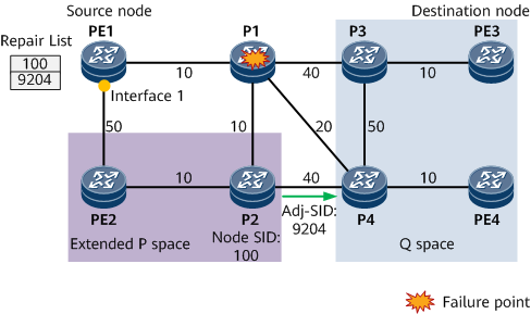
The following uses node protection as an example to describe how to implement TI-LFA. Assume that traffic travels along the PE1 -> P1 -> P3 -> PE3 path on the network shown in Figure 3. To prevent traffic loss caused by P1 failures, TI-LFA computes the extended P space, Q space, post-convergence SPT to be used after P1 fails, backup outbound interface, and repair list, and then generates backup forwarding entries.
Computes the extended P space {PE2, P2} with PE1's neighbor PE2 as the root node.
Computes the Q space {P3, P4, PE3, PE4} with P3 as the root node.

In this example, the end node on the traffic forwarding path is PE3, which has only one egress (P3). As such, to simplify calculation, P3 can be used as the root.
Computes the post-convergence SPT by excluding the primary next hop.
- Computes a backup outbound interface and a repair list.
Backup outbound interface: If the extended P space and Q space neither intersect nor have direct neighbors, the post-convergence next-hop outbound interface functions as the backup outbound interface.
Repair list: a constrained path through which traffic can be directed to a Q node. The repair list consists of a P node label (SID) and a P-to-Q adjacency label. In Figure 3, the repair list consists of P2's node label 100 and the P2-to-P4 adjacency label 9204.
- The node SID advertised by the repair node is preferentially selected. If the repair node does not advertise a node SID, a prefix SID advertised by the repair node is preferentially selected. The smaller the prefix SID, the higher the priority.
- A node that does not support SR or does not advertise any prefix or node SID cannot function as the repair node.
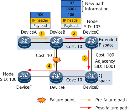
TI-LFA FRR Forwarding
After a TI-LFA backup path is computed, if the primary path fails, traffic is switched to the backup path, preventing packet loss.
Assume that a packet carrying the prefix SID 16100 of PE3 needs to be forwarded from PE1 to PE3 over the PE1 -> P1 -> P3 -> PE3 path shown in Figure 4. When the primary next hop P1 fails, TI-LFA FRR is triggered, switching traffic to the backup path.
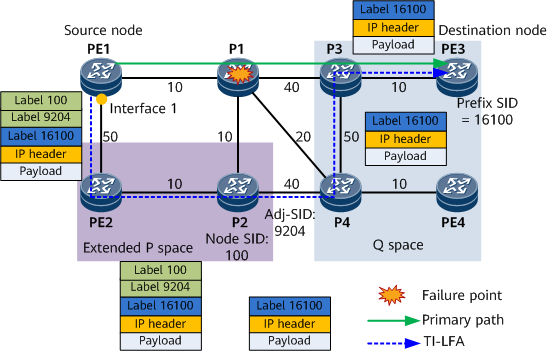
The process of forwarding a packet over a TI-LFA FRR backup path is as follows:
- PE1 encapsulates a label stack into the packet based on the repair list, using P2's node label 100 as the outer label and the P2-to-P4 adjacency label 9204 as the inner label.
- After receiving the packet, PE2 searches its label forwarding table according to the outer label 100 and then forwards the packet to P2.
- After receiving the packet, P2 searches its label forwarding table according to the outer label. Because P2 is the egress node, it removes the label 100 to expose the label 9204, which is an adjacency SID allocated by P2. As such, P2 finds the corresponding outbound interface according to the label 9204, removes the label, and then forwards the remaining packet content to P4.
- After receiving the packet, P4 searches its label forwarding table according to the outer label 16100 and then forwards the packet to P3.
- After receiving the packet, P3 searches its label forwarding table according to the outer label 16100 and then forwards the packet to PE3.
- After receiving the packet, PE3 searches its label forwarding table according to the outer label and determines that the label 16100 is a local label. Therefore, PE3 removes the label. As 16100 is the bottommost label, PE3 performs further packet processing according to IP packet header information.
TI-LFA FRR Usage Scenarios
TI-LFA FRR Protection |
Description |
Deployment |
|---|---|---|
TI-LFA FRR protects traffic transmitted in IP forwarding mode. |
Traffic is transmitted over the primary path in IP forwarding mode, and a TI-LFA FRR backup path is computed. |
|
TI-LFA FRR protects traffic transmitted over an SR tunnel. |
Traffic is transmitted over a primary SR tunnel, and a TI-LFA FRR backup path is computed. |
|
Advantages of TI-LFA FRR
- Meets basic requirements for IP FRR fast convergence.
- Theoretically supports all scenarios.
- Uses an algorithm of moderate complexity.
- Directly uses a post-convergence path as the backup forwarding path, involving no intermediate convergence state like other FRR technologies.