IS-IS Auto FRR
Background
As networks develop, services such as Voice over IP (VoIP) and online video services require high-quality and real-time transmission. However, if a link fails, IS-IS must complete the following procedure before switching traffic to a new link: detect the fault, update LSPs, flood LSPs, calculate routes, and deliver route entries to the FIB. This is a lengthy process, and the associated traffic interruption is often longer than users can tolerate. As a result, real-time transmission requirements cannot be met.
IS-IS Auto fast re-route (FRR) is a dynamic IP FRR technology that minimizes traffic loss by immediately switching traffic to the alternate link pre-computed by an IGP based on the LSDBs on the entire network and stored in the FIB if a link or adjacent node failure is detected. As IP FRR implements route convergence, it is becoming increasingly popular with carriers.
Major Auto FRR techniques include loop-free alternate (LFA), U-turn, Not-Via, TI-LFA, Remote LFA, and MRT, among which IS-IS supports only LFA, TI-LFA, and Remote LFA.
Related Concepts
LFA
LFA is an IP FRR technology that calculates the shortest path from the neighbor that can provide an alternate link to the destination node based on the Shortest Path First (SPF) algorithm. Then, LFA calculates a loop-free alternate link with the smallest cost based on the inequality: Distance_opt (N, D) < Distance_opt (N, S) + Distance_opt (S, D).
In the preceding inequality, S, D, and N indicate the source node, destination node, and a neighbor of S, respectively, and Distance_opt (X, Y) indicates the shortest distance from node X to node Y.
P space
P space consists of the nodes through which the shortest path trees (SPTs) with the source node of a primary link as the root are reachable without passing through the primary link.
Extended P space
Extended P space consists of the nodes through which the SPTs with neighbors of a primary link's source node as the root are reachable without passing through the primary link.
Q space
Q space consists of the nodes through which the SPTs with the destination node of a primary link as the root are reachable without passing through the primary link.
PQ node
A PQ node exists both in the extended P space and Q space and is used by Remote LFA as the destination of a protection tunnel.
Remote LFA
LFA Auto FRR cannot be used to calculate alternate links on large-scale networks, especially on ring networks. Remote LFA Auto FRR addresses this problem by calculating a PQ node and establishing a tunnel between the source node of a primary link and the PQ node. If the primary link fails, traffic can be automatically switched to the tunnel, which improves network reliability.

When calculating an RLFA FRR backup path, a Huawei device calculates the extended P space by default.
TI-LFA
When computing a TI-LFA FRR backup path, Huawei devices compute the extended P space by default.
For more information about TI-LFA, see TI-LFA FRR.
IS-IS LFA Auto FRR
Link protection: Link protection applies to traffic transmitted over specified links.
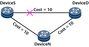
In the example network shown in Figure 1, traffic flows from DeviceS to DeviceD, and the link cost meets the preceding link protection inequality. If the primary link (DeviceS -> DeviceD) fails, DeviceS switches the traffic to the alternate link (DeviceS -> DeviceN -> DeviceD), minimizing traffic loss.
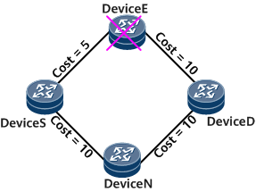
Node-and-link protection: Node-and-link protection applies to traffic transmitted over specified nodes or links. Figure 2 illustrates a network where LFA Auto FRR node-and-link protection is used. Node-and-link protection takes precedence over link protection.
Node-and-link protection takes effect when the following conditions are met:The link cost satisfies the inequality: Distance_opt (N, D) < Distance_opt (N, S) + Distance_opt (S, D).
The interface cost of the device satisfies the inequality: Distance_opt (N, D) < Distance_opt (N, E) + Distance_opt (E, D).
S indicates the source node of traffic, E indicates the faulty node, N indicates the node on the backup link, and D indicates the destination node of traffic.
IS-IS Remote LFA Auto FRR
Similar to IS-IS LFA Auto FRR, Remote LFA is also classified as link protection or node-and-link protection. The following example shows how Remote LFA works to protect against link failures:
In Figure 3, traffic flows through PE1 -> P1 -> P2 -> PE2, and the primary link is between P1 and P2. Remote LFA calculates a PQ node (P4) and establishes a Label Distribution Protocol (LDP) tunnel between P1 and P4. If P1 detects a failure on the primary link, P1 encapsulates packets into MPLS packets and forwards MPLS packets to P4. After receiving the packets, P4 removes the MPLS label from them and searches the IP routing table for a next hop to forward the packets to PE2. Remote LFA ensures uninterrupted traffic forwarding.
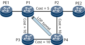
Calculate an SPT with each of P1's neighbors (excluding the neighbor on the protection link) as the root. In this case, use the neighbors PE1 and P3 for calculation. For each SPT, an extended P space is composed of the root node and those reachable nodes that belong to the SPT but do not pass through the P1→P2 link. When PE1 is used as a root node for calculation, the extended P space {PE1, P1, P3} is obtained. When P3 is used as a root node for calculation, the extended P space {PE1, P1, P3, P4} is obtained. By combining these two extended P spaces, the final extended P space {PE1, P1, P3, P4} is obtained.
Calculates a reverse SPT with P2 as the root. The Q space is composed of the root node's directly connected nodes and the root node. Therefore, the Q space is {P2, PE2, P4}.
Determines the PQ node that is in both the extended P space and Q space. Therefore, the PQ node is P4 in this example.
IPv6 IS-IS Remote LFA Auto FRR protects IPv6 traffic and uses IPv4 LDP LSPs. The principle of IPv6 IS-IS Remote LFA Auto FRR is similar to that of IPv4 IS-IS Remote LFA Auto FRR.
IS-IS FRR in the Scenario Where Multiple Nodes Advertise the Same Route
IS-IS LFA FRR uses the SPF algorithm to calculate the shortest path to the destination node, with each neighbor that provides a backup link as the root node. The backup next hop is node-based, which applies to single-node routing scenarios, that is, scenarios where a route is received from only one node. With the diversification of networks, multi-node routing scenarios appear, where multiple nodes advertise the same route. Such scenarios do not meet single-node LFA conditions. As a result, the backup next hop cannot be calculated. IS-IS FRR for multi-node routing scenarios can address this problem by using a routing source to protect the primary routing source and improve network reliability.
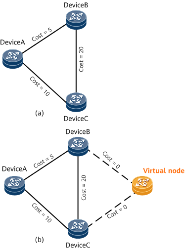
In Figure 4 (a), the cost of the link between Device A and Device B is 5, whereas the cost of the link between Device A and Device C is 10. Both Device B and Device C advertise the route 10.1.1.0/24. IS-IS FRR is enabled on Device A. However, single-node LFA conditions are not met. As a result, Device A fails to calculate the backup next hop of the route 10.1.1.0/24. IS-IS FRR for multi-node routing scenarios can address this problem.
In Figure 4 (b), a virtual node is simulated between Device B and Device C and is connected to Device B and Device C. The cost of the link from Device B or Device C to the virtual node is 0, whereas the cost of the link from the virtual node to Device B or Device C is the maximum value. After the virtual node advertises the route 10.1.1.0/24, Device A uses the LFA algorithm to calculate the backup next hop of the virtual node. Then the route 10.1.1.0/24 inherits the backup next hop from the virtual node. In this example, the primary link to the virtual node is the one from Device A to Device B, and the backup link is the one from Device A to Device C.
IS-IS ECMP FRR
Equal cost multi path (ECMP) evenly balances traffic over multiple equal-cost paths to the same destination.
If the ECMP FRR function is not supported in ECMP scenarios, no backup next hop can be calculated for primary links.
IS-IS ECMP FRR is enabled by default, and a backup next hop is calculated separately for each primary link, which enhances reliability in ECMP scenarios. With ECMP FRR, IS-IS pre-calculates backup paths for load balancing links based on the LSDBs on the entire network. The backup paths are stored in the forwarding table and are used for traffic protection in the case of link failures.
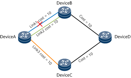
In Figure 5, traffic is forwarded from Device A to Device D and is balanced among link 1, link 2, and link 3. Backup paths of the three links are calculated based on ECMP FRR. For example, the backup paths of link 1, link 2, and link 3 are link 3, link 3, and link 2, respectively.
- If the ECMP FRR function is not enabled in the load balancing scenario and link 1 fails, traffic over link 1 is randomly switched to link 2 or link 3, which affects service traffic management.
- If the ECMP FRR function is enabled in the load balancing scenario and link 1 fails, traffic over link 1 is switched to link 3 according to FRR route selection rules, which enhances service traffic management.
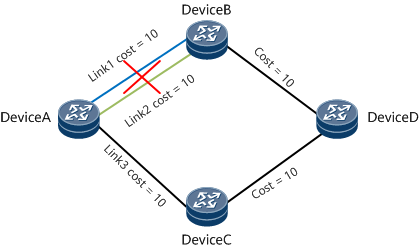
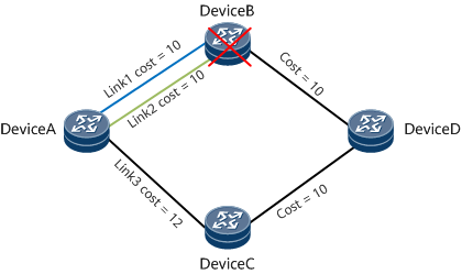
In Figure 6, traffic is forwarded from Device A to Device D and is balanced between link 1 and link 2. Backup paths of the two links are calculated based on ECMP FRR. For example, the backup paths of link 1 and link 2 are both link 3.
- If the ECMP FRR function is not enabled in the load balancing scenario and Device B fails, link 1 and link 2 fail accordingly, leading to a traffic interruption.
- If the ECMP FRR function is enabled in the load balancing scenario and Device B fails, link 1 and link 2 fail accordingly. However, traffic is switched to link 3, which prevents the traffic interruption.
IS-IS SRLG FRR
A shared risk link group (SRLG) is a set of links that share a common physical resource, such as an optical fiber. These links share the same risk level. If one of the links fails, all the other links in the SRLG may also fail.
On the network shown in Figure 7, traffic between Device A and Device D is balanced by Link 1 and Link 2.
- If Link 1 fails but Link 2 is normal, traffic is not interrupted after being switched to the backup link.
- If both Link 1 and Link 2 fail, traffic is interrupted after being switched to the backup link.
IS-IS SRLG FRR prevents service interruptions in the scenario where links have the same risk of failure. To implement IS-IS SRLG FRR, add the links having the same risk of failure to the same SRLG, and configure IS-IS to preferentially select a backup link not in the same SRLG during route calculation in Auto FRR.