SR-MPLS TE Policy Creation
An SR-MPLS TE Policy can be manually configured on a forwarder through CLI or NETCONF. Alternatively, it can be delivered to a forwarder after being dynamically generated by a protocol, such as BGP, on a controller. The dynamic mode facilitates network deployment. If SR Policies generated in both modes exist, the forwarder selects an SR-MPLS TE Policy based on the following rules in descending order:
- Protocol-Origin: The default value of Protocol-Origin is 20 for a BGP-delivered SR-MPLS TE Policy and is 30 for a manually configured SR-MPLS TE Policy. A larger value indicates a higher preference.
- <ASN, node-address> tuple: ASN indicates an AS number. For both ASN and node-address, a smaller value indicates a higher preference. The ASN and node-address values of a manually configured SR-MPLS TE Policy are fixed at 0 and 0.0.0.0, respectively.
- Discriminator: A larger value indicates a higher preference. For a manually configured SR-MPLS TE Policy, the value of Discriminator is the same as the preference value.
Manual SR-MPLS TE Policy Configuration
You can manually configure an SR-MPLS TE Policy through CLI or NETCONF. For a manually configured SR-MPLS TE Policy, information, such as the endpoint and color attributes, the preference values of candidate paths, and segment lists, must be configured. Moreover, the preference values must be unique. The first-hop label of a segment list can be a node, adjacency, BGP EPE, parallel, or anycast SID, but cannot be any binding SID. Ensure that the first-hop label is a local incoming label, so that the forwarding plane can use this label to search the local forwarding table for the corresponding forwarding entry.
Figure 1 Manually configured SR-MPLS TE Policy

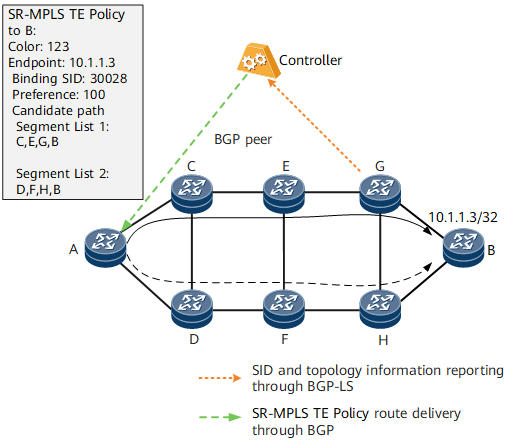
SR-MPLS TE Policy Delivery by a Controller
Figure 2 shows the process in which a controller dynamically generates and delivers an SR-MPLS TE Policy to a forwarder. The process is as follows:
- The controller collects information, such as network topology and label information, through BGP-LS.
- The controller and headend forwarder establish a BGP peer relationship in the IPv4 SR-MPLS TE Policy address family.
- The controller computes an SR-MPLS TE Policy and delivers it to the headend forwarder through the BGP peer relationship. The headend forwarder then generates SR-MPLS TE Policy entries.