Traffic Steering into an SR-MPLS TE Policy
Route Coloring
Route coloring is to add the Color Extended Community to a route through a route-policy, enabling the route to recurse to an SR-MPLS TE Policy based on the color value and next-hop address in the route.
Configure a route-policy and set a specific color value for the desired route.
Apply the route-policy to a BGP peer or a VPN instance as an import or export policy.
Color-based Traffic Steering
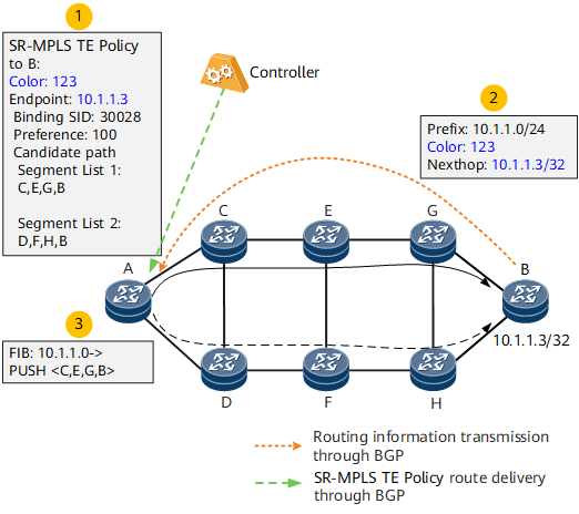
- The controller delivers an SR-MPLS TE Policy to headend device A. The SR-MPLS TE Policy's color value is 123 and its endpoint value is the address 10.1.1.3 of device B.
- A BGP or VPN export policy is configured on device B, or a BGP or VPN import policy is configured on device A, with the color value being set to 123 for route prefix 10.1.1.0/24 and the next-hop address in the route being set to address 10.1.1.3 of device B. Then, the route is delivered to device A through the BGP peer relationship.
- A tunnel policy is configured on device A. After receiving BGP route 10.1.1.0/24, device A recurses the route to the SR-MPLS TE Policy based on color value 123 and next-hop address 10.1.1.3. During forwarding, the label stack <C,E,G,B> is added to the packets destined for 10.1.1.0/24.
DSCP-based Traffic Steering
DSCP-based traffic steering does not support color-based route recursion. Instead, it recurses a route into an SR-MPLS TE Policy based on the next-hop address in the route. Specifically, it searches for the SR-MPLS TE Policy group matching specific endpoint information and then finds the corresponding SR-MPLS TE Policy based on the DSCP value of packets. Figure 2 shows the DSCP-based traffic steering process.
- The controller sends two SR Policies to headend device A. SR-MPLS TE Policy 1's color value is 123 and its endpoint value is address 10.1.1.3 of device B. SR-MPLS TE Policy 2's color value is 124 and its endpoint value is also address 10.1.1.3 of device B.
- Device B delivers BGP route 10.1.1.0/24 to headend device A through the BGP peer relationship.
- Tunnel policy configuration is performed on the head device A. Specifically, an SR-MPLS TE Policy group is configured, with its endpoint being address 10.1.1.3 of device B. Color value 123 is mapped to DSCP value 10, and color value 124 is mapped to DSCP value 20. Then, a tunnel policy is configured on device A to bind the SR-MPLS TE Policy group and the next-hop address in the route.
- Device A implements tunnel recursion based on the destination address of packets and finds the SR-MPLS TE Policy group bound to the destination address. After the color value matching the DSCP value of the packets and the specific SR-MPLS TE Policy matching the color value are found, the packets can be steered into the SR-MPLS TE Policy.

