SR-MPLS TE Policy-based Data Forwarding
Intra-AS Data Forwarding

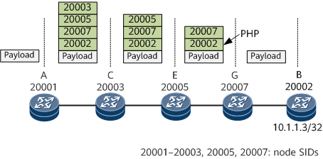
- The controller delivers an SR-MPLS TE Policy to headend device A.
- Endpoint device B advertises BGP route 10.1.1.0/24 to device A, and the next-hop address in the BGP route is address 10.1.1.3/32 of device B.
- A tunnel policy is configured on ingress A. After receiving the BGP route, device A recurses the route to the SR-MPLS TE Policy based on the color and next-hop address in the route. The label stack of the SR-MPLS TE Policy is <20003, 20005, 20007, 20002>.
Inter-AS Data Forwarding
Inter-AS data forwarding depends on the establishment of inter-AS SR-MPLS TE Policy forwarding entries. Figure 3 shows the process of establishing inter-AS SR-MPLS TE Policy forwarding entries.

- The controller delivers an intra-AS SR-MPLS TE Policy to headend device ASBR3 in AS 200. The SR-MPLS TE Policy's color value is 123, endpoint is IP address 10.1.1.3 of PE1, and binding SID is 30028.
- The controller delivers an inter-AS E2E SR-MPLS TE Policy to headend device CSG1 in AS 100. The SR-MPLS TE Policy's color value is 123, and endpoint is address 10.1.1.3 of PE1. The segment list combines the intra-AS label of AS 100, the inter-AS BGP Peer-Adj label, and the binding SID of AS 200, forming <102, 203, 3040, 30028>.
- A BGP or VPN export policy is configured on PE1, with the color value being set to 123 for route prefix 10.1.1.0/24 and the next-hop address in the route being set to address 10.1.1.3 of PE1. Then, the route is advertised to CSG1 through the BGP peer relationship.
- A tunnel policy is configured on headend device CSG1. After receiving BGP route 10.1.1.0/24, CSG1 recurses the route to the E2E SR-MPLS TE Policy based on the color value and next-hop address in the route. The label stack of the SR-MPLS TE Policy is <102, 203, 3040, 30028>.
Figure 4 shows the inter-AS data forwarding process.

The inter-AS SR-MPLS TE Policy data forwarding process is as follows:
Headend device CSG1 adds label stack <102, 203, 3040, 30028> to the data packet. Then, the device searches for the outbound interface according to label 102 of the CSG1->AGG1 adjacency and removes the label. The packet carrying label stack <203, 3040, 30028> is forwarded to downstream device AGG1 through the CSG1->AGG1 adjacency.
After receiving the packet, AGG1 searches for the adjacency matching top label 203 in the label stack, finds that the corresponding outbound interface is the AGG1->ASBR1 adjacency, and removes the label. The packet carrying label stack <3040, 30028> is forwarded to downstream device ASBR1 through the AGG1->ASBR1 adjacency.
After receiving the packet, ASBR1 searches for the adjacency matching top label 3040 in the label stack, finds that the corresponding outbound interface is the ASBR1->ASBR3 adjacency, and removes the label. The packet carrying label stack <30028> is forwarded to downstream device ASBR3 through the ASBR1->ASBR3 adjacency.
After receiving the packet, ASBR3 searches the forwarding table based on top label 30028 in the label stack. 30028 is a binding SID that corresponds to label stack <405, 506>. Then, the device searches for the outbound interface based on label 405 of the ASBR3->P1 adjacency and removes the label. The packet carrying label stack <506> is forwarded to downstream device P1 through the ASBR3->P1 adjacency.
After receiving the packet, P1 searches for the adjacency matching top label 506 in the label stack, finds that the corresponding outbound interface is the P1->PE1 adjacency, and removes the label. In this case, the packet does not carry any label and is forwarded to destination device PE1 through the P1->PE1 adjacency. After receiving the packet, PE1 further processes it based on the packet destination address.