MPLS in UDP
MPLS in UDP Fundamentals

MPLS in UDP is a DCN overlay technology that encapsulates MPLS packets (or SR-MPLS packets) into UDP packets to traverse through some networks that do not support MPLS or SR-MPLS. MPLS in UDP solves the problem of bearer protocol conversion between the DCN and WAN and unifies the tunnel protocols run on the DCN and WAN.
Device 1 encapsulates VMa1-to-VMb1 packets and sends them to DCN GW1.
Upon receipt of the packets, GW1 on DCN A encapsulates SR-MPLS information into VXLAN packets based on the path computation results of the controller. Because MAN A does not support SR, GW1 has to encapsulate the SR-MPLS packets using UDP and diverts the UDP packets to the MPLS-in-UDP tunnel. The MAN forwards the UDP packets to DCI-PE1.
After receiving the SR-MPLS packets, DCI-PE1 forwards the packets to DCI-PE2 using SR-MPLS TE.
DCI-PE2 forwards the packets to MAN B over IP routes.
MAN B forwards the packets to GW2 over IP routes.
GW2 forwards the packets to Device 3 over IP routes. Upon receipt of the packets, Device 3 decapsulates the packets and sends them to VMb1.
To prevent UDP packets from being attacked, MPLS in UDP technology supports source IP address verification. The source IP address is the IP address of the ingress of the MPLS-in-UDP tunnel. The packets are accepted only when the source IP addresses are successfully verified. Otherwise, the packets are discarded. In Figure 1, source IP address verification is enabled on DCI-PE1 that is the egress of the MPLS-in-UDP tunnel. After DCI-PE1 receives the MPLS-in-UDP packets, DCI-PE1 verifies the contained source IP addresses, which improves transmission security.
If a device serves as the egress nodes of different MPLS-in-UDP tunnels, a valid source IP address list must be configured based on specified local IP addresses.
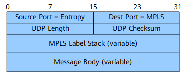
Format of an MPLS-in-UDP Packet
Field Name |
Length |
Description |
|---|---|---|
Source Port = Entropy |
16 bits |
Source interface number, which is generated by a device that encapsulates packets |
Dest Port = MPLS |
16 bits |
Destination interface number, which is fixed at 6635 indicating an MPLS-in-UDP interface |
UDP Length |
16 bits |
UDP packet size |
UDP Checksum |
16 bits |
UDP checksum |
MPLS Label Stack |
Variable length |
Depth of an MPLS label stack |
Message Body |
Variable length |
Size of MPLS packet content |