SRv6 SFC Implementation
SFC Definition
Service Function Chain (SFC) logically connects services on network devices to provide an ordered service set for the application layer. By adding service function path (SFP) information in original packets, SFC enables packets to pass through service functions (SFs) along a specified path.
Data packets on a network usually pass through various SFs to provide users with secure, fast, and stable services as planned. These SFs include firewalls, intrusion prevention systems (IPSs), application accelerators, and network address translation (NAT) devices. User-required services can be implemented only when network traffic passes through SFs in a sequence defined by the service logic.
Basic SFC Concepts
Depending on SRv6 encapsulation awareness, SFs are classified into SRv6-aware and SRv6-unaware SFs.
SRv6-aware SFs can identify and process received SRv6 packets. In this case, the SIDs of SFs are directly added into SFPs to implement SFC.
SRv6-unaware SFs cannot identify SRv6 packets and therefore discard them once received. In this case, SF proxies must be configured to implement SFC.

This section focuses on SFC implementation by SRv6-unaware SFs. Unless otherwise specified, SFs mentioned later all refer to SRv6-unaware SFs.
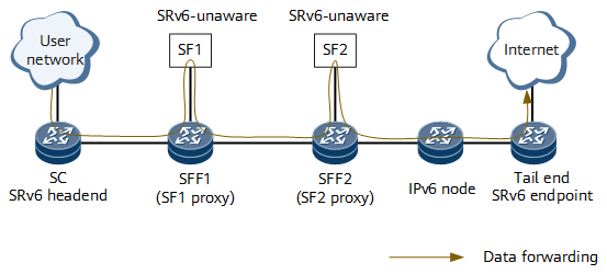
Figure 1 shows typical SRv6 SFC networking.
Table 1 describes other SFC concepts.
Concept |
Description |
|---|---|
SFC domain |
A domain where SFs are deployed. |
Service classifier (SC) |
Located at the ingress of an SFC domain, an SC classifies traffic entering the domain. The classification granularity can be coarse or fine, depending on the SC capability and SFC policy. |
Service function forwarder (SFF) |
An SFF forwards received packets to its associated SFs based on SRv6 encapsulation information. After processing the packets, these SFs return the packets to the SFF, which then determines whether to send the packets back to the network. Because SFs cannot process SRv6 packets, SF proxies are required. An SF proxy processes packets from an SFF on behalf of an SF. Specifically, the SF proxy deletes SRv6 encapsulation information and then sends the packets to the represented SF using the local logical component. The SF proxy also receives packets from the SF and then re-adds SRv6 encapsulation information to the packets. In Figure 1, the SFFs function as SF proxies. |
Service function path (SFP) |
An SFP is calculated based on configurations and precisely defines the location of each SF. On an SRv6 network, an SRv6 TE Policy can function as an SFP. |
SRv6 TE Policy-based SFC Forwarding
By using segment lists, an SRv6 TE Policy instructs network devices to forward traffic along a specified path. This mechanism is suitable for implementing SFC. After a data packet is redirected into an SRv6 TE Policy, the headend adds the segment lists of the SRv6 TE Policy to the data packet, and other devices on the network execute the instructions embedded in the segment lists.
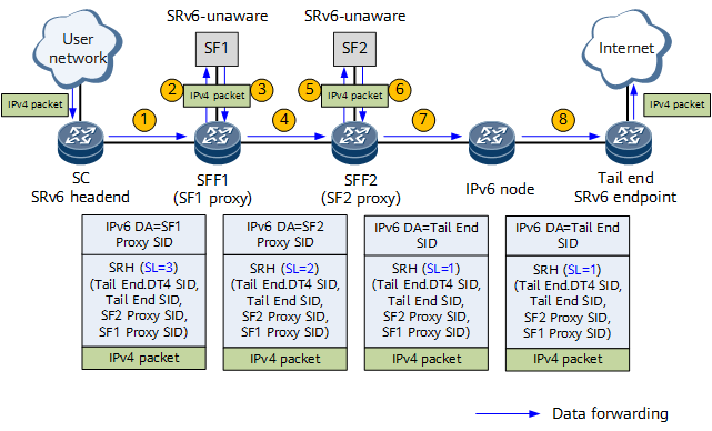
As shown in Figure 2, SF1 and SF2 are SRv6-unaware SFs. To implement SFC, SF proxy must be configured on SFF1 and SFF2, and SRv6 SIDs must be allocated to SF1 and SF2 proxies. On the SC, the SF1 Proxy SID, SF2 Proxy SID, and Tail End SID form a segment list of an SRv6 TE Policy. The SRv6 TE Policy functions as an SFP.
- After receiving an original IPv4 packet from a user network, the SC classifies the packet based on 5-tuple information and redirects the classified traffic to an SRv6 TE Policy. Based on the SRv6 TE Policy, the SC encapsulates the packet into an SRv6 packet, with the SF1 Proxy SID as the destination address. In Figure 2, in addition to containing SRv6 TE Policy information, the SRH contains the Tail End.DT4 SID that represents VPN or public network services.
- After receiving the SRv6 packet, SFF1 executes the instruction corresponding to the SF1 Proxy SID by decapsulating the packet and sending the original packet to SF1 for processing.
- After processing the packet, SF1 sends the packet back to SFF1.
- Based on information about the interface through which SFF1 receives the IPv4 packet, SFF1 searches for the relevant configuration. After finding the configuration, SFF1 encapsulates the packet into an SRv6 packet by re-adding SRH information according to the configuration. The destination address of the SRv6 packet is the SF2 Proxy SID.
- After receiving the SRv6 packet, SFF2 executes the instruction corresponding to the SF2 Proxy SID by decapsulating the packet and sending the original packet to SF2 for processing.
- After processing the packet, SF2 sends the packet back to SFF2.
- Based on information about the interface through which SFF2 receives the IPv4 packet, SFF2 searches for the relevant configuration. After finding the configuration, SFF2 encapsulates the packet into an SRv6 packet by re-adding SRH information according to the configuration. The destination address of the SRv6 packet is the Tail End SID. The packet is then forwarded to the tail end node along the shortest IGP path.
- After receiving the SRv6 packet, the tail end finds that the destination address of the packet is its own End SID. The tail end then executes the instruction corresponding to the End SID by decapsulating the packet, decreasing the Segment Left (SL) field value by 1 (meaning that the value changes to 0), and updating the IPv6 destination address field. The IPv6 destination address field of the current packet is the Tail End.DT4 SID. The tail end searches My Local SID Table for an instruction matching the Tail End.DT4 SID, and then executes the instruction to forward the original IPv4 packet to the corresponding IPv4 VPN or public network.

