SRv6 SFC Reliability
SFC services are forwarded in serial mode, meaning that a single link or node failure causes SFC service interruptions. To improve service reliability, SRv6 SFC provides backup link protection and bypass link protection.
- In backup link protection, an SF is dual-homed to two SFFs, with one as the master, and the other as the backup. The backup SFF protects the master SFF. If the master SFF becomes unreachable, services are switched to the backup SFF.
- In bypass link protection, if an SF is unreachable, SFC traffic is switched to the bypass service path, without being processed by the current SF. An SFF usually discards SFC packets if an SF is unreachable. After bypass link protection is configured, SFC packets can continue to be forwarded as follows:
- If no bypass SF is available for the current SF, SRv6 forwarding is implemented for SFC packets.
- If the current SF has a bypass SF to provide protection, SFC packets are switched to the bypass SF for processing.
The protection schemes can be selected according to specific SFC networking scenarios. The following describes their applications.
SFC Scenario with a Single-Homed SF That Does Not Have a Bypass SF
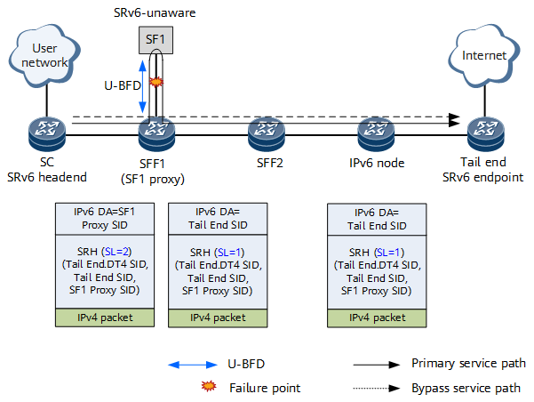
On the network shown in Figure 1, SF1 is single-homed to SFF1 and has no bypass SF. Unaffiliated BFD (U-BFD) is configured on SFF1 to detect SF1 reachability. When BFD detects that SF1 is unreachable, the SF1 Proxy SID is skipped, and the next Tail End SID is used to perform SRv6 forwarding.
SFC Scenario with a Single-Homed SF That Has a Bypass SF
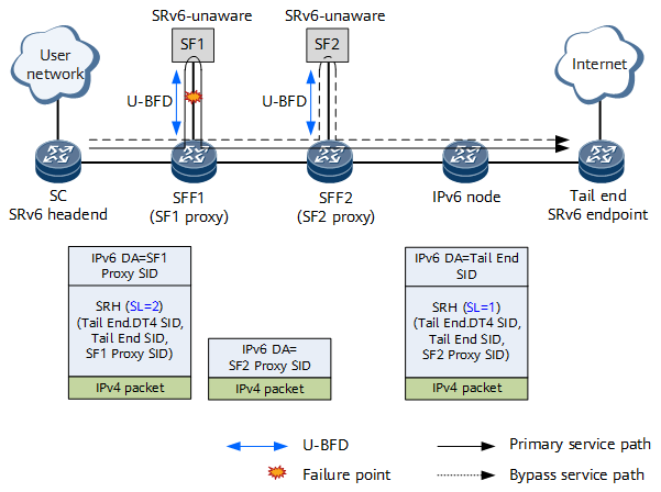
On the network shown in Figure 2, SF1 is single-homed to SFF1 and has a bypass SF – SF2. A bypass protection path is configured for the SF1 Proxy SID. The SF2 Proxy SID is configured on SFF2.
U-BFD is configured on SFF1 to detect SF1 reachability. When BFD detects that SF1 is unreachable, the SFC traffic is switched to the bypass service path. SFF1 removes the SRH and searches the IPv6 routing table for packet forwarding, using the SF2 Proxy SID as the destination IPv6 address. After receiving the packet, SFF2 forwards it to SF2 based on the SF2 Proxy SID.
SFC Scenario with a Dual-Homed SF That Does Not Have a Bypass SF
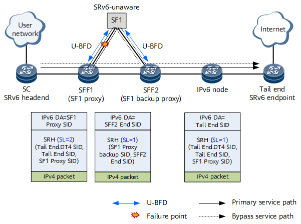
On the network shown in Figure 3, SF1 is dual-homed to SFF1 and SFF2, and has no bypass SF.
In this case, a backup path needs to be configured for protection. Because SF1 is dual-homed to SFF1 and SFF2, SFF1 and SFF2 can provide protection for each other. Specifically, the same SF1 Proxy SID of the End.AS type needs to be configured on SFF1 and SFF2 to implement the anycast function. (For ease of description, the SF1 Proxy SID on SFF2 in Figure 3 is called SF1 Backup Proxy SID.) In addition, SFF1 and SFF2 need to be configured as peers of each other. The peer SID of SFF1 is the End SID of SFF2, and the peer SID of SFF2 is the End SID of SFF1.
U-BFD also needs to be configured on SFF1 to detect SF1 reachability. When BFD detects that SF1 is unreachable, the SFC traffic is switched to the backup service path. SFF1 replaces the original SRv6 segment list with the SF1 Proxy Backup SID and SFF2 End SID, and forwards the SFC packet to SFF2. After receiving the packet, SFF2 identifies that both the SF1 Proxy Backup SID and SFF2 End SID are its own SIDs. SFF2 then forwards the packet to SF1 based on the SF1 Proxy Backup SID. After the packet returns from SF1 to SFF2, SFF2 re-encapsulates the initial SRv6 segment list of the packet based on the configuration and forwards the packet to a downstream device.
SFC Scenario with a Dual-Homed SF That Has a Bypass SF
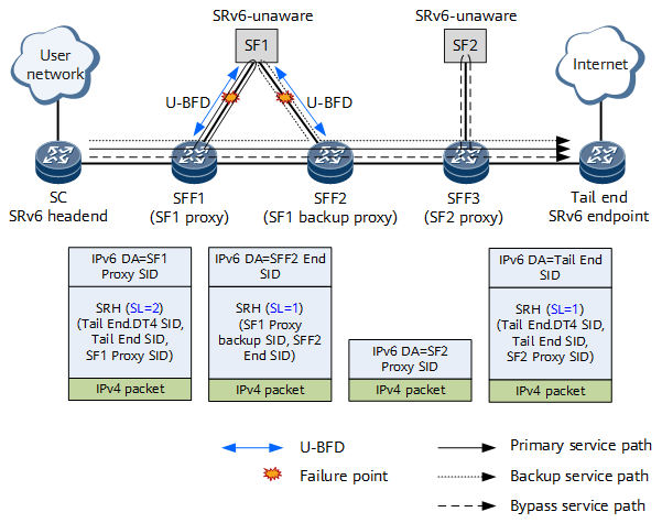
On the network shown in Figure 4, SF1 is dual-homed to SFF1 and SFF2, and has a bypass SF – SF2.
In this case, a backup path needs to be configured for protection. Because SF1 is dual-homed to SFF1 and SFF2, SFF1 and SFF2 can provide protection for each other. Specifically, the same SF1 Proxy SID of the End.AS type needs to be configured on SFF1 and SFF2 to implement the anycast function. (For ease of description, the SF1 Proxy SID on SFF2 in Figure 4 is called SF1 Backup Proxy SID.) In addition, SFF1 and SFF2 need to be configured as peers of each other. The peer SID of SFF1 is the End SID of SFF2, and the peer SID of SFF2 is the End SID of SFF1.
U-BFD is configured on SFF1 to detect SF1 reachability. When BFD detects that SF1 is unreachable, the SFC traffic is switched to the backup service path. SFF1 replaces the original SRv6 segment list with the SF1 Proxy Backup SID and SFF2 End SID, and forwards the SFC packet to SFF2. After receiving the packet, SFF2 identifies that both the SF1 Proxy Backup SID and SFF2 End SID are its own SIDs. SFF2 then forwards the packet to SF1 based on the SF1 Proxy Backup SID.
If U-BFD on SFF2 detects that SF1 is unreachable, the SFC traffic is switched to the bypass service path. SFF2 removes the SRH and searches the IPv6 routing table for packet forwarding, using the SF2 Proxy SID as the destination IPv6 address. After receiving the packet, SFF3 forwards it to SF2 based on the SF2 Proxy SID.


