BGP for SRv6
IGP for SR allocates SIDs only within an autonomous system (AS). Proper SID orchestration in an AS facilitates the planning of an optimal path in the AS. However, IGP for SR does not work if paths cross multiple ASs on a large-scale network. BGP for SRv6 is an extension of BGP for Segment Routing. This function enables a device to allocate BGP peer SIDs based on BGP peer information and report the SID information to a controller. An SRv6 TE Policy uses BGP peer SIDs for path orchestration, thereby obtaining the optimal inter-AS path. BGP for SRv6 mainly involves the BGP egress peer engineering (EPE) extension and BGP-LS extension.
BGP EPE
A Peer-Node SID identifies a peer node. The peers at both ends of each BGP session are assigned Peer-Node SIDs. An EBGP peer relationship established based on loopback interfaces may traverse multiple physical links. In this case, the Peer-Node SID of a peer is mapped to multiple outbound interfaces. Traffic can be forwarded through any outbound interface or be load-balanced among multiple outbound interfaces.
A Peer-Adj SID identifies an adjacency to a peer. An EBGP peer relationship established based on loopback interfaces may traverse multiple physical links. In this case, each adjacency is assigned a Peer-Adj SID. Only a specified link (mapped to a specified outbound interface) can be used for forwarding.

On the network shown in Figure 1, ASBR1 and ASBR3 are directly connected through two physical links. An EBGP peer relationship is established between ASBR1 and ASBR3 through loopback interfaces. ASBR1 runs BGP EPE to allocate the Peer-Node SID 2001:DB8::1 to its peer (ASBR3) and to allocate the Peer-Adj SIDs 2001:DB8:1::2 and 2001:DB8:1::3 to the physical links. For EBGP peers that are directly connected through physical interfaces, BGP EPE allocates only Peer-Node SIDs rather than Peer-Adj SIDs. For example, on the network shown in Figure 1, BGP EPE allocates only Peer-Node SIDs 2001:DB8::4, 2001:DB8::5, and 2001:DB8::6 to ASBR1-ASBR5, ASBR2-ASBR4, and ASBR2-ASBR5, respectively.
Peer-Node SIDs and Peer-Adj SIDs are both local SIDs. That is, they are only effective on a local device, and other devices may use the same Peer-Node SID and Peer-Adj SID. Currently, BGP EPE supports IPv6 EBGP and IBGP peers.
BGP EPE allocates SIDs only to BGP peers and links, but cannot be used to construct a forwarding path. BGP peer SIDs must be used with IGP SIDs to form an E2E path.
BGP Virtual Link
On the network shown in Figure 2, an EBGP or multi-hop IBGP peer relationship is established between R1 and P1, and corresponding link information can be reported to the controller through BGP-LS. For example, R1 generates a piece of link information containing the local address 2001:DB8:2::1 and the remote address 2001:DB8:2::2, whereas P1 generates a piece of link information containing the local address 2001:DB8:2::2 and the remote address 2001:DB8:2::1. These two pieces of link information match each other. After parsing the received link information, the controller obtains corresponding peer information and then combines the two pieces of link information to form complete link information for E2E SR path computation. The implementation between P2 and R3 is similar to that between R1 and P1. R1 and R3 establish a BGP peer relationship and are not directly connected. They communicate across a third-party network (an external network providing IPv6 L3VPN services) and achieve IP reachability through P1 and P2. Although R1 and R3 can also report link information through BGP-LS, the addresses in the link information reported by one device do not match those reported by the other device. As a result, the controller cannot combine the two pieces of link information reported by these devices. To complete E2E SRv6 TE Policy deployment in this case, configure a BGP peer relationship-based virtual link (highlighted in blue in Figure 2) between R1 and R3. The local and remote IPv6 addresses of the virtual link must be the same as those used to establish the BGP peer relationship. Attributes, including link latency, metric, affinity, and SRLG attributes, can be configured for SRv6 TE Policy path computation.

BGP-LS
Field |
Description |
|---|---|
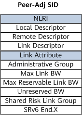
NLRI |
Network layer reachability information. It consists of the following parts:
|
Link Attribute |
Link information. It is a part of the Link NLRI.
|
Field |
Description |
|---|---|
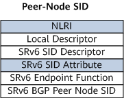
NLRI |
Network layer reachability information. It consists of the following parts:
|
SRv6 SID Attribute |
SRv6 SID attribute information. It is a part of the SRv6 SID NLRI.
|
Field |
Length |
Description |
|---|---|---|
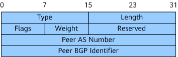
Type |
16 bits |
TLV type. |
Length |
16 bits |
Packet length. |
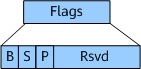
Flags |
8 bits |
Flags field used in an SRv6 BGP Peer-Node SID TLV. Figure 6 shows the format of this field.
In this field:
|
Weight (not currently supported) |
8 bits |
SID weight used for load balancing purposes. |
Peer AS Number |
32 bits |
BGP AS number of the peer router. |
Peer BGP Identifier |
32 bits |
BGP identifier of the peer router. |