SRv6 SRH Compression
Impact of the SRv6 SRH Length
Segment Routing Header (SRH) is a key extension for SRv6 implementation. In the encapsulation mode, an SRv6 ingress may encapsulate an outer IPv6 header and an SRH into a packet before forwarding the packet. This can increase header overhead. If there are a large number of SRv6 SIDs, the SRH length increases further, which may cause the following issues:
- Payload efficiency reduction: The header added in SRv6 acts as a transmission overhead. When there are a large number of SIDs in the SRH, the header length increases and the payload proportion decreases. This results in low payload efficiency.
- Hardware forwarding performance deterioration: As the number of SIDs increases, the SID stack depth in SRv6 packets may exceed the depth read by hardware each time. As a result, the hardware must read a second time, causing forwarding performance to deteriorate.
- Packet forwarding restricted by the MTU: After the SRv6 header is added, the size of packets may exceed the MTU, causing packet fragmentation or loss.
Generalized SRv6 Network Programming (G-SRv6) is an SRv6-compatible SRH compression solution. It not only supports SRH compression to reduce the overhead of SRv6 headers, but also supports smooth transition from non-compression solutions to compression solutions because G-SRv6 SIDs can be programmed in the same SRH with conventional SRv6 SIDs.
G-SRv6 involves SRv6 SRH compression and compatibility with SRv6.
- In SRv6 SRH compression, redundant information in the segment list is removed from the SRH based on the regularity of the SRv6 SID format and allocation. So the SRH carries only different parts of SRv6 SIDs, reducing the header overhead.
- In compatibility with SRv6, a flavor is introduced to indicate the format of the next SID, processing SIDs of different lengths and in turn supporting hybrid programming and processing of different types of SIDs.
G-SID
SIDs in an SRv6 domain are allocated from a SID address block and therefore have a common prefix (CP). If the SID in the destination address of the IPv6 header carries the common prefix, the SIDs in the SRH only need to carry the different parts. As such, when the address is updated, only the different parts are replaced to restore the original SID. In G-SRv6, the different parts are called the generalized SID (G-SID). Figure 1 shows the relationship between a complete SID and a G-SID.
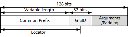
As shown in Figure 1, multiple SRv6 SIDs can have the same prefix (common prefix), which can also be referred to as the locator block. The G-SID consists of the locator's Node ID and the following Function ID. In an actual network design, the total length of the common prefix and G-SID may be less than 128 bits. In this case, the remaining bits can be padded with 0s.
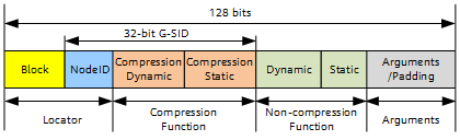
To implement SRv6 SRH compression, an SRv6 SID needs to be divided using the Locator:Compression Function:Non-compression Function:Arguments format. Figure 2 shows the SRv6 SID format in compression scenarios.
G-SID Container
To be compatible with the SRH, G-SIDs need to be arranged to align with 128 bits in the SRH. That is, four 32-bit G-SIDs or multiple G-SIDs of other lengths need to be arranged in a 128-bit unit. If the length is less than 128 bits, 0s are used to pad it to 128 bits. Therefore, the G-SRv6 solution defines G-SID containers to indicate 128-bit units. Each G-SID container is a 128-bit value and can contain a common SRv6 SID or multiple G-SIDs (for example, one to four 32-bit G-SIDs). Figure 3 shows the possible format of a G-SID container with 32-bit G-SIDs.
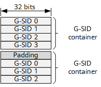
A G-SID container is 128 bits long, the same as an existing SRv6 SID, and can be used to encapsulate multiple G-SIDs. The G-SID-based network programming solution, which is called generalized SRv6 (G-SRv6), is an upgrade of SRv6.
G-SRH Encapsulation
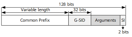
To support hybrid encoding of a G-SID and an SRv6 SID in an SRH, a generalized SID index (SI) pointer is added to the two least significant bits of the Arguments field after the G-SID in an IPv6 destination address to identify the location of the G-SID in a G-SID container. When the length of the G-SID is 32 bits, the SI pointer is located in the two least significant bits of the Arguments field. In this case, if the total length of the Common Prefix, G-SID, and Arguments fields is 128 bits, the SI pointer is located in the two least significant bits of the 128 bits, as shown in Figure 4.
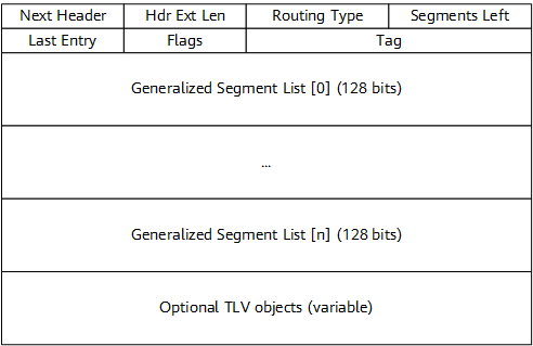
G-SRv6 extends only the format of a SID that can be carried in an SRH, and does not change the definitions of the original fields in the standard SRH. Such an SRH can carry multiple types of G-SID containers and is therefore called the generalized SRH (G-SRH). Figure 5 shows the G-SRH format.
To satisfy the programming requirements of the controller or ingress, a C flag needs to be added to identify whether the SID can be compressed when a SID is advertised. Such a SID is called a compressible SRv6 SID.
During segment list processing, a continuation of compression (COC) flavor needs to be introduced to express the need of updating the next 32-bit G-SID to the DA field. By default, a SID that does not carry the COC flavor indicates that the length of the next SID is 128 bits.
The controller or ingress can encode the segment list based on the C flag and COC flavor of the SIDs.
After receiving a packet, an endpoint can update the IPv6 destination address based on the COC flavor of the SID and the SI value, and perform a corresponding forwarding action based on the instruction of the SID.
G-SRv6 Implementation
G-SRv6 supports the compression of an SRH and the hybrid programming of SRv6 SIDs and G-SIDs on an SRv6 network.
Figure 6 shows the forwarding process of the G-SRv6 solution when packets traverse SRv6 compression and non-compression domains.

Assume that SIDs and IP addresses are allocated as follows:
- The IP addresses of CE1 and CE2 are X (10.1.0.1) and Y (10.2.0.1), respectively.
- The SRv6 path originating from node A uses the source address A::1.
- Node B allocates an SRv6 End.DT4 SID of B::100 to VPN 100.
- An End SID of D::k:1 is allocated to node Dk in the SRv6 non-compression domain.
- An End SID of C::k:1:0:SI is allocated to node Ck in the SRv6 compression domain, and the Common Prefix is C::/64. The 32-bit G-SID k:1 carries the COC flavor, whereas the G-SID k:2 does not. The G-SID is followed by the 32-bit Arguments field, and the SI pointer is located in the two least significant bits of this field.
- k specifies the ID of a node in the topology.
Assume that the optimal path from CE1 to CE2 is A->D1->D2->D3->D4->C1->C2->C3->C4->B. When the G-SRv6 solution is used, the G-SRv6 path can be divided into the following sub-paths: D1->D2->D3->D4 in the SRv6 non-compression domain and C1->C2->C3->C4 in the SRv6 compression domain.
The sub-path in the SRv6 non-compression domain can be represented as a list formed by four SRv6 SIDs (D::1:1, D::2:1, D::3:1, D::4:1), and the sub-path in the SRv6 compression domain can be represented as a list formed by one SRv6 G-SID and one compression G-SID (C::1:1:0:0, <2:1, 3:1, 4:2, Padding>).
Figure 7 (a) and Figure 7 (b) show the packet formats corresponding to the two sub-paths.

Figure 8 shows the complete G-SRH in an SRv6 packet.

Use Figure 6 as an example. Figure 9 shows how the data packets sent from CE1 to CE2 traverse SRv6 non-compression and compression domains.
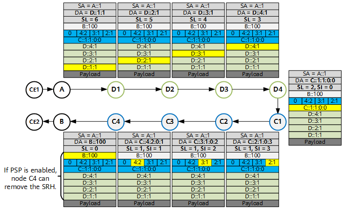
Data packet processing on the network is as follows:
- After receiving a data packet, node A performs G-SRv6 encapsulation on the packet, using D::1:1 as the destination address and 6 as the SL value in the G-SRH. Node A searches the IPv6 routing table, and forwards the packet to node D1 based on the destination address D::1:1.
- Node D1 determines that the destination address is a local SRv6 End SID, performs the End behavior to update the packet, and then searches the IPv6 routing table to forward the packet to node D2. In this packet, the SL value in the G-SRH is 5.
- Nodes D2, D3, and D4 perform the same actions upon receipt of the packet. The destination address of the packet sent by node D4 to node C1 is C::1:1:0:0, the SL value in the G-SRH is 2, and the SI value in the destination address is 0.
- After receiving the packet, node C1 determines that the destination address C::1:1:0:0 is the local SRv6 End SID that carries the COC flavor. In this case, because the SI value is 0, node C1 decrements the SL value to 1, assigns the value 3 to SI, and reads SRH[SL=1][SI=3] based on SL and SI to obtain the G-SID 2:1.
Node C1 then updates 2:1 to the corresponding position in the IPv6 destination address, and changes the SI value in the last two bits of the destination address to 3, obtaining the new IPv6 destination address C::2:1:0:3.
Node C1 searches the IPv6 routing table based on C::2:1:0:3 and forwards the packet to node C2.
- After receiving the packet, node C2 determines that the destination address is the local SRv6 End SID that carries the COC flavor. In this case, because the SI value is greater than 0, node C2 decrements the SI value to 2 and obtains the G-SID 3:1 based on SL and SI.
Node C2 then updates 3:1 to the corresponding position in the IPv6 destination address, changes the SI value in the last two bits of the destination address to 2 to obtain the new destination address C::3:1:0:2, and forwards the packet to node C3 by searching the IPv6 routing table.
- The processing on node C3 is similar to that on node C2. For the packet sent from node C3 to node C4, the destination address is C::4:2:0:1, the SL value in the G-SRH is 1, and the SI value in the destination address is 1.
- After receiving the packet, node C4 determines that the destination address is a local compressible SRv6 End SID. In this case, because C::4:2:0:1 does not carry the COC flavor, node C4 decrements the SL value and updates the next 128-bit G-SID B::100 to the IPv6 destination address, with the SL value in the G-SRH being 0.
Node C4 then searches the IPv6 routing table to forward the packet to node B. In addition, if C::4:2:0:1 carries the PSP flavor, node C4 performs the PSP operation to remove the G-SRH from the packet.
- After receiving the packet, node B determines that the destination address is a local SRv6 End.DT4 SID, performs IPv6 decapsulation, searches the routing table of VPN 100 based on the destination address of the inner packet, and finally forwards the packet to CE2.
SRH Compression Efficiency
In Figure 6, the SRH originally contains nine SIDs (four SIDs for D1 to D4, another four SIDs for C1 to C4, and one VPN SID). The total size of the non-compression SRH is 144 bytes (9 x 16). As shown in Figure 8, after the four SIDs of C1 to C4 in the compression domain are compressed, the total size of the compression SRH becomes 112 bytes (7 x 16). This means that the SRH is reduced by 32 bytes (144 – 112), rendering a compression efficiency of 22% (32/144).
In an ideal pure compression scenario where the SIDs of the nodes in the same SRv6 domain have the same prefix (called common prefix), the compression efficiency varies depending on the number of SIDs in an SRH. Table 1 details the SRH compression efficiency.
Number of SIDs |
Length of the Non-compression SRH (Bytes) |
Length of the Compression SRH (Bytes) |
Reduction in SRH Length (Bytes) (Formula: Length of the non-compression SRH – Length of the compression SRH) |
Compression Efficiency (Formula: Reduction in SRH length/Length of the non-compression SRH) |
|---|---|---|---|---|
1 |
16 |
16 |
0 |
0 |
2 |
32 |
32 |
0 |
0 |
3 |
48 |
32 |
16 |
About 33.33% |
4 |
64 |
32 |
32 |
50% |
5 |
80 |
32 |
48 |
60% |
6 |
96 |
48 |
48 |
50% |
7 |
112 |
48 |
64 |
About 57.14% |
8 |
128 |
48 |
80 |
62.50% |
9 |
144 |
48 |
96 |
About 66.67% |
10 |
160 |
64 |
96 |
60% |

An SRv6 TE Policy typically supports a maximum of 10 hops. Therefore, Table 1 only details the compression efficiency of SRHs with one to 10 SIDs.
The first SID in the compression SRH cannot be compressed because it is used to help subsequent compressed SIDs restore their complete formats. Except the first SID that is not compressed, every four subsequent SIDs can be compressed into a 128-bit G-SID. If the G-SID contains less than 128 bits, it can be padded with 0s.
The lengths of the non-compression SRH and compression SRH do not include the fixed length of 40 bytes in the SRv6 header.
G-SRv6 Characteristics
G-SRv6 has the following characteristics:
- Compatible with SRv6/SRH.
- Address planning:
- SIDs need to use the same Locator Block.
- Existing SRv6 address blocks can be reused.
- The prefix length is flexible. Short prefixes are not required, and address blocks are easy to obtain.
- Control plane: G-SRv6 requires an enhancement to SRv6 protocol extensions. The C flag and COC flavor need to be advertised together with SID information.
- New protocol extensions need to be introduced in the control plane.
- SID entries need to be added.
- SIDs with multiple behaviors can be compressed.
- Forwarding-plane protocol extension: G-SRv6 does not change the SRv6 SRH encapsulation format but adds processing logic for the COC flavor.
- Forwarding entry: G-SRv6 requires corresponding SID entries to be added for G-SIDs.
- Routing information is simple. No route needs to be added when G-SIDs and common SRv6 SIDs share a locator.
- Address space utilization is high.
- Compression efficiency is high, reducing the length of a segment list to about 25% of the original length.
- Forwarding performance is high. G-SID replacement has little impact on forwarding performance.