SRv6 Flex-Algo
Traditionally, IGPs can use only the SPF algorithm to calculate the shortest paths to destination addresses based on link costs. As the SPF algorithm is fixed and cannot be adjusted by users, the optimal paths cannot be calculated according to users' diverse requirements. For example, it cannot support traffic forwarding along the lowest-delay path or without passing through certain links.
On a network, constraints used for path calculation may be different. For example, as autonomous driving requires an ultra-low delay, an IGP needs to use delay as the constraint to calculate paths on such a network. Another constraint that needs to be considered is cost, so some links with high costs need to be excluded in path calculation. These constraints may also be combined.
To make path calculation more flexible, users may want to customize IGP route calculation algorithms to meet their varying requirements. They can define an algorithm value to identify a fixed algorithm. When all devices on a network use the same algorithm, their calculation results are also the same, preventing loops. Since users, not standards organizations, are the ones to define these algorithms, they are called Flexible Algorithms (Flex-Algos).
With Flex-Algos, an IGP can automatically calculate eligible paths based on the link cost, delay, or TE constraint to flexibly meet TE requirements. This means that when SRv6 uses an IGP to calculate paths, locators can be associated with Flex-Algos to calculate SRv6 BE paths that meet different requirements.
SRv6 Flex-Algo Advertisement
Each device can use an IGP to advertise their supported Flex-Algos and the related calculation rules through the FAD Sub-TLV.
These Flex-Algos can also be associated with locators during locator configuration. The IGP then advertises the Flex-Algos and locators through the SRv6 Locator TLV.
The Flex-Algo value occupies 8 bits in the FAD Sub-TLV and SRv6 Locator TLV. Values 128 to 255 are reserved for users to customize the Flex-Algos represented by these values.
To ensure that the forwarding path calculated by an IGP is loop free, the same Flex-Algo must be used in an IGP domain. IS-IS advertises its Flex-Algo Definition (FAD) through the IS-IS FAD Sub-TLV.
IS-IS FAD Sub-TLV
IS-IS uses the IS-IS Router Capability TLV-242 to carry the IS-IS FAD Sub-TLV and advertises the sub-TLV to neighbors. Figure 1 shows the format of the IS-IS FAD Sub-TLV.
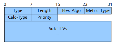
Table 1 describes the fields in the IS-IS FAD sub-TLV.
Field |
Length |
Description |
|---|---|---|
Type |
8 bits |
Type of the sub-TLV. |
Length |
8 bits |
Total length of the sub-TLV (excluding the Type and Length fields). |
Flex-Algo |
8 bits |
Flex-Algo ID, which is an integer ranging from 128 to 255. |
Metric-Type |
8 bits |
Metric type used during calculation. This field can be set to an IGP metric, minimum unidirectional link delay, or TE metric value. |
Calc-Type |
8 bits |
Calculation type, which can currently only be SPF and does not need setting. |
Priority |
8 bits |
Priority of the sub-TLV. |
Sub-TLVs |
Variable |
Optional sub-TLVs, which can define some constraints. |
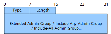
- Exclude Admin Group: A link is excluded from path calculation if any bit in the link's administrative group has the same name as an affinity bit referenced by the administrative group.
- Include-Any Admin Group: A link is included in path calculation as long as one bit in the link's administrative group has the same name as an affinity bit referenced by the administrative group.
- Include-All Admin Group: A link is included in path calculation only if all bits in the link's administrative group have the same names as the affinity bits referenced by the administrative group.
These constraints are described by the Sub-TLVs field in the FAD Sub-TLV and share the same format, as shown in Figure 2.
- The FAD with the highest priority is preferentially selected.
- If the priorities of the FADs advertised by devices are the same, the FAD advertised by the device with the largest system ID is selected.
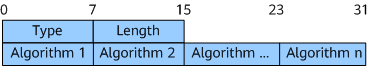
SR-Algorithm Sub-TLV
A node may use different algorithms to calculate reachability to other nodes or to prefixes attached to these nodes. Examples of these algorithms are SPF and various SPF variant algorithms. The SR-Algorithm sub-TLV allows the node to advertise the algorithms that the node is currently using. It is also inserted into the IS-IS Router Capability TLV-242 for transmission. The SR-Algorithm sub-TLV can be propagated only within the same IS-IS level and must not be propagated across IS-IS levels.
Field |
Length |
Description |
|---|---|---|
Type |
8 bits |
Unassigned. The recommended value is 2. |
Length |
8 bits |
Packet length. |
Algorithm |
8 bits |
Algorithm that is used. |
SRv6 Flex-Algo Implementation
Figure 4 is used as an example to describe how SRv6 Flex-Algo is implemented.
A device using Flex-Algos for path calculation must advertise its Flex-Algos to other devices. Where:
- PE1 and PE2 use both Flex-Algos 128 and 129, which are advertised to all the other nodes on the network through an IGP's SR-Algorithm Sub-TLVs.
- P1 to P4 use Flex-Algo 128, which is also advertised through the IGP.
- P5 to P8 use Flex-Algo 129, which is also advertised through the IGP.
Besides Flex-Algos 128 and 129, all devices support the most basic IGP cost-based algorithm, which has value 0. This algorithm is not advertised through the FAD Sub-TLV.
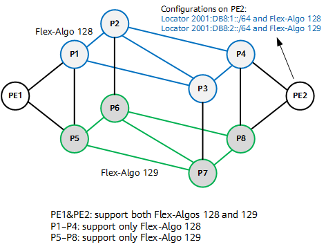
After a locator is associated with a Flex-Algo on PE2, other devices on the network calculate the network segment route corresponding to the locator based on the Flex-Algo. As this configuration method repeats, different locator routes that represent different paths calculated using different Flex-Algos can be generated, meeting diverse service requirements.
For example, in Figure 4, Flex-Algo 128 is defined as follows: calculate a path based on the IGP cost and link affinity, with the constraint being Exclude Admin Group (excluding the links between P2 and P3 as well as between P2 and P4). Figure 5 shows the possible path obtained on PE1 with this Flex-Algo.
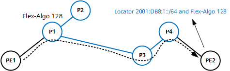
Flex-Algo-based SRv6 BE Path
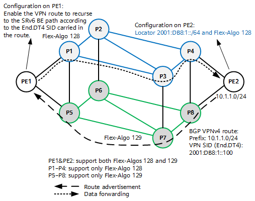
Figure 6 shows the process of steering service traffic into a Flex-Algo-based SRv6 BE path. The implementation process is as follows:
- Configure PE1 and PE2 to use both Flex-Algos 128 and 129; configure P1 to P4 to use Flex-Algo 128, and P5 to P8 to use Flex-Algo 129.
- Configure locator 2001:DB8:1::/64 to use Flex-Algo 128 on PE2. In this way, the locator route is associated with the Flex-Algo.
- Configure BGP to advertise the VPNv4 route with prefix 10.1.1.0/24 on PE2. The End.DT4 SID of the VPN instance is 2001:DB8:1::100.
- The IGP on PE1 uses Flex-Algo 128 to calculate a route to locator 2001:DB8:1::/64.
- The VPN route on PE1 is recursed to the Flex-Algo-based SRv6 BE path according to the End.DT4 SID carried in the route by following the longest match rule.
Flex-Algo-based SRv6 TE Policy
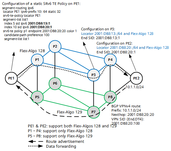
Figure 7 shows the implementation of a Flex-Algo-based SRv6 TE Policy. The implementation process is as follows:
- Configure PE1 and PE2 to use both Flex-Algos 128 and 129; configure P1 to P4 to use Flex-Algo 128, and P5 to P8 to use Flex-Algo 129.
- On PE2, configure locator 2001:DB8:20::/64 to use Flex-Algo 128 and configure End SID 2001:DB8:20::1.
On P3, configure locator 2001:DB8:13::/64 to use Flex-Algo 128 and configure End SID 2001:DB8:13::1.
The IGPs on other devices use Flex-Algo 128 to calculate two routes for locator 2001:DB8:13::/64 and locator 2001:DB8:20::/64.
- Configure BGP to advertise the VPNv4 route with prefix 10.1.1.0/24 on PE2. The End.DT4 SID of the VPN instance is 2001:DB8:20::100.
- Configure an SRv6 TE Policy on PE1 and set the segment list of the SRv6 TE Policy to <End SID 2001:DB8:13::1, End SID 2001:DB8:20::1>.
- Configure a tunnel policy on PE1. After receiving the BGP VPNv4 route, PE1 recurses it to the corresponding SRv6 TE Policy based on its color and next hop.
In the data forwarding phase:
After receiving a common unicast packet destined for 10.1.1.0/24, PE1 searches the routing table of the corresponding VPN instance for a matching route and finds that the outbound interface of the route is an SRv6 TE Policy. PE1 then encapsulates an SRH with the SRv6 TE Policy segment list <End SID 2001:DB8:13::1, End SID 2001:DB8:20::1> and an outer IPv6 header with the destination IPv6 address 2001:DB8:13::1 into the packet. After that, PE1 searches the IPv6 routing table based on 2001:DB8:13::1 and forwards the packet along the shortest path calculated by the IGP based on Flex-Algo 128.
- Upon receipt of the packet, P3 searches My Local SID Table based on the destination IPv6 address 2001:DB8:13::1 of the packet and finds that the packet matches the End SID. P3 then decrements the SL value of the packet by 1 and updates the IPv6 DA to 2001:DB8:20::1. After that, P3 searches the IPv6 routing table based on 2001:DB8:20::1 and forwards the packet along the shortest path calculated by the IGP based on Flex-Algo 128.
After the packet arrives at PE2, PE2 searches My Local SID Table for a matching SID based on the destination IPv6 address 2001:DB8:20::1 in the packet. According to the instruction bound to the SID, PE2 decrements the SL value of the packet by 1 and updates the IPv6 DA to 2001:DB8:20::100.
PE2 searches My Local SID Table for a matching End.DT4 SID based on 2001:DB8:20::100. According to the instruction bound to the SID, PE2 decapsulates the packet by popping the SRH and outer IPv6 header, searches the routing table of the VPN instance corresponding to the VPN SID 2001:DB8:20::100 based on the destination address in the inner packet, and forwards the packet.