Fundamentals of Network Slicing
Network Slice Planning
Slice IDs are core elements of network slicing. Before planning network slices, you need to create network slice instances and allocate slice IDs. A physical network is divided into multiple network slices by dividing interface forwarding resources.
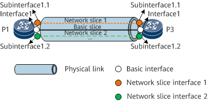
On the network shown in Figure 1, network slice instances are created on P1 and P3, network slice interfaces are planned and bound to the network slice instances, and forwarding resources such as bandwidth are reserved.
According to Figure 1, plan all devices on the entire network. The physical network can be divided into required logical slices, as shown in Figure 2.

Network Slice-based Service Forwarding
In an SRv6 scenario, End SIDs are allocated only to nodes on the physical network, and End.X SIDs are allocated to physical links. No SID is allocated to logical nodes or links on network slices, and the SIDs of the physical network are directly used.
As shown in Figure 3, an L3VPNv4 over SRv6 TE Policy is used as an example to describe the route transmission process.
During route transmission, PE2 can transmit VPN routes to PE1 through the MP-BGP/BGP EVPN peer relationship. The route information carries information such as the color, next hop, and VPN SID.
Create an SRv6 TE Policy on PE1 in advance, configure a slice ID for the SRv6 TE Policy, and associate the SRv6 TE Policy with the slice ID. PE1 recurses the VPN route 10.2.2.2/32 to the SRv6 TE Policy based on the color and next hop information, and transmits data to the specified network slice for forwarding based on the slice ID of the SRv6 TE Policy.

Figure 4 shows the data forwarding process of an L3VPNv4 over SRv6 TE Policy.

In the data forwarding phase:
- CE1 sends a common IPv4 unicast packet to PE1.
After receiving the packet from CE1, PE1 searches the routing table of the corresponding VPN instance and finds that the outbound interface of the route is an SRv6 TE Policy. PE1 inserts SRH information into the packet and performs the following encapsulations in sequence: encapsulates the SID list of the SRv6 TE Policy, encapsulates the HBH header that carries the slice ID of the SRv6 TE Policy, and encapsulates the IPv6 basic header. PE1 then finds the network slice interface based on the slice ID and forwards the packet to P1 over this interface.
P1 forwards the packet based on the SRH information. During forwarding, P1 uses the slice ID information in the HBH header to associate the packet with the specified network slice interface. The forwarding process on P3 and P5 is similar to that on P1.
After the packet arrives at the egress PE2, PE2 searches the My Local SID Table based on the IPv6 destination address in the packet and finds a matching End SID. According to the instruction bound to the SID, PE2 decrements the SL value of the packet by 1 and updates the IPv6 DA field to the VPN SID.
Based on the VPN SID, PE2 searches the My Local SID Table for a matching End.DT4 SID. According to the instruction bound to the SID, PE2 decapsulates the packet, removes the SRH, HBH header, and IPv6 header, searches the routing table of the VPN instance corresponding to the VPN SID based on the destination address 10.2.2.2 in the inner IPv4 packet, and forwards the packet to CE2.
It can be learned from the foregoing process that slice IDs are essential for connecting the control and forwarding planes. Therefore, this network slicing solution is also referred to as slice ID-based network slicing. For details, see Figure 5.
