SRv6 TE Policy Shortcut
Background
Currently, SRv6 TE Policies and SRv6 TE flow groups are mainly deployed in specific network areas for purposes such as traffic acceleration and load balancing. Sometimes, traffic traversing network areas cannot be effectively steered into the desired SRv6 TE Policy or SRv6 TE flow group, resulting in an SLA guarantee failure.
The SRv6 TE Policy shortcut function considers an SRv6 TE Policy or SRv6 TE flow group a local direct link. This allows an IGP to use the SRv6 TE Policy or SRv6 TE flow group as an outbound interface to calculate routes and steer data traffic to the SRv6 TE Policy or SRv6 TE flow group for forwarding, meeting SLA requirements.
Implementation of the Shortcut Function for SRv6 TE Policies
An IGP uses an SRv6 TE Policy as a local direct link to perform enhanced SPF calculation. If the headend and endpoint of the SRv6 TE Policy match the ingress and egress of a physical link on the SPF tree, respectively, the IGP uses the SRv6 TE Policy to replace the physical link, implementing the shortcut function for the SRv6 TE Policy.
Although a device on which the shortcut function for SRv6 TE Policies is enabled uses an SRv6 TE Policy as an outbound interface, it does not advertise the SRv6 TE Policy to its neighbors. As such, other devices cannot use the SRv6 TE Policy.
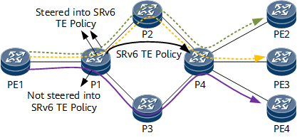
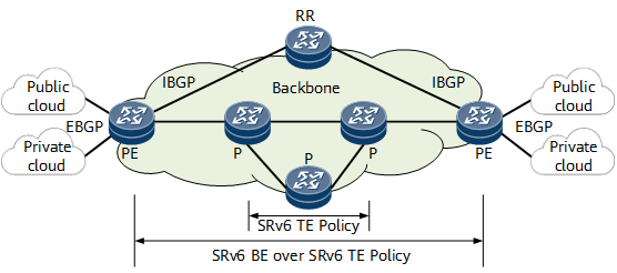
On the network shown in Figure 1, when implementing the shortcut function, an IGP can steer all of the traffic destined for different addresses to an SRv6 TE Policy. For example, if the shortest paths from PE1 to PE2, PE3, and PE4 all need to pass through the link P1-P2-P4, all of the traffic destined for PE2, PE3, and PE4 can be steered into the SRv6 TE Policy on P1. Alternatively, you can configure a route-policy to steer traffic destined for a specified address to an SRv6 TE Policy. For example, you can configure a route-policy on P1 to steer only the traffic from PE1 to PE2/PE3 to the SRv6 TE Policy, while allowing the traffic from PE1 to PE4 to be forwarded through a native IP link.
Implementation of the Shortcut Function for Static SRv6 TE Flow Groups
An SRv6 TE flow group is a set of SRv6 TE Policies and can be used to implement DSCP-based traffic steering. It contains multiple SRv6 TE Policies with the same endpoint but different color values. During service recursion, service traffic is matched against SRv6 TE Policies in the SRv6 TE flow group according to the DSCP values carried by the traffic.
The mapping between DSCP values and SRv6 TE Policies can be statically configured in an SRv6 TE flow group and applies to both IPv4 and IPv6 services. Only an SRv6 TE Policy in the up state can be mapped to a DSCP value.
In the implementation of the shortcut function for a static SRv6 TE flow group, the SRv6 TE flow group is considered a local direct link. An IGP uses the SRv6 TE flow group as an outbound interface to perform enhanced SPF calculation. If the headend and endpoint of the SRv6 TE flow group match the ingress and egress of a physical link on the SPF tree, respectively, the IGP uses the SRv6 TE flow group to replace the physical link, implementing the shortcut function for the SRv6 TE flow group. During data forwarding, a node steers data traffic into the corresponding SRv6 TE flow group based on DSCP values, thereby meeting SLA requirements.
Although a device on which the shortcut function for SRv6 TE flow groups is enabled uses an SRv6 TE flow group as an outbound interface, it does not advertise the SRv6 TE flow group to its neighbors. As such, other devices cannot use the SRv6 TE flow group.
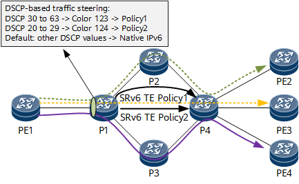
Traffic is differentiated based on DSCP values, which determine the SRv6 TE Policy into which traffic is steered. You can perform configuration to allow traffic carrying DSCP values that do not match any SRv6 TE Policy to be forwarded over IPv6 by default. For details, see Figure 2.
Data Forwarding Process
On the network shown in Figure 3, in the data forwarding phase, CE1 forwards an IPv6 packet to PE1. After receiving the packet, PE1 steers it into the corresponding SRv6 TE Policy according to the outbound interface of the involved IGP route or the DSCP value of the packet.
PE1 encapsulates SRv6 TE Policy data into the IPv6 packet, and transit nodes P1 and P2 forward the packet according to the segment list information of the SRv6 TE Policy.
After receiving the packet, the endpoint PE2 decapsulates it and removes the IPv6 header according to the USD flavor carried in the End SID 2001:DB8:40::4. PE2 then searches the IPv6 routing table based on the destination IPv6 address in the inner packet and forwards the packet to CE2.

Typical Application of the Shortcut Function for SRv6 TE Policies
International Internet Traffic Acceleration
Assume that there is international Internet traffic on the network shown in Figure 4. SRv6 TE Policies are deployed on the IP backbone network and the shortcut function is enabled. If an SPF path of an IGP route overlaps with an SRv6 TE Policy, traffic can be steered into the SRv6 TE Policy. In real-world applications, VIP customer traffic can be steered into the SRv6 TE Policy with the lowest latency to speed up the transmission of international Internet services.
Typical Application of the Shortcut Function for SRv6 TE Flow Groups
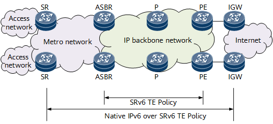
Traffic Acceleration on a Cloud Backbone Network
Figure 5 shows multiple cloud data centers that are interconnected through a cloud backbone network. There are a wide range of services with different SLA requirements.
Static SRv6 TE flow groups are deployed on the core part of the cloud backbone network to prevent network congestion. Each SRv6 TE flow group contains multiple SRv6 TE Policies. In addition, SRv6 BE is deployed for E2E services, which have traffic classification implemented.
To ensure the quality of various services forwarded over SRv6 BE, you can configure the involved devices to distinguish service types through traffic classification, map the services to DSCP values, and then steer packets with different DSCP values to the corresponding SRv6 TE Policies.
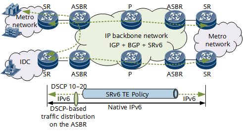
IP Bearer Network Evolution
As shown in Figure 6, the IP backbone network uses an IGP and BGP as control-plane protocols and SRv6 as the data-plane protocol, making the network programmable and simple while also unifying protocols.
To meet differentiated service requirements, BGP routes are used to implement E2E service connectivity. Packets that carry matching DSCP values are steered into corresponding SRv6 TE Policies for forwarding, and packets that do not carry matching DSCP values are forwarded over common IPv6.