Example for Configuring L3VPNv4 over SRv6 BE ECMP
This section provides an example for configuring L3VPNv4 over SRv6 BE ECMP.
Networking Requirements
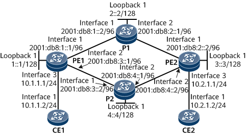
PE1, PE2, P1, and P2 are in the same AS and run IS-IS to implement IPv6 network connectivity.
PE1, P1, P2, and PE2 are Level-2 devices that belong to IS-IS process 1.
It is required that a bidirectional SRv6 BE path be deployed between PE1 and PE2 to carry L3VPNv4 services. In addition, to maximize network resource utilization, it is required that ECMP be performed for L3VPNv4 services carried by the SRv6 BE path between PE1 and PE2.
Precautions
During the configuration process, note the following:
SRv6 BE ECMP depends on equal-cost routes on the network. To ensure successful configuration, you need to properly plan IGP costs for links. In this example, each link uses the default cost value 10.
Configuration Roadmap
The configuration roadmap is as follows:
Enable IPv6 forwarding and configure an IPv6 address for each interface on PE1, P1, P2, and PE2.
Enable IS-IS, configure an IS-IS level, and specify a network entity on PE1, P1, P2, and PE2. In addition, configure dynamic BFD for IPv6 IS-IS.
Configure VPN instances on PE1 and PE2.
Establish an EBGP peer relationship between each PE and its connected CE.
Establish an MP-IBGP peer relationship between PEs.
Configure SRv6 on PE1 and PE2, and enable IS-IS SRv6.
Data Preparation
To complete the configuration, you need the following data:
IPv6 address of each interface on PE1, P1, P2, and PE2
IS-IS process ID of PE1, P1, P2, and PE2
IS-IS level of PE1, P1, P2, and PE2
VPN instance name, RD, and RT on PE1 and PE2
Procedure
- Enable IPv6 forwarding and configure an IPv6 address for each interface. The following example uses the configuration of PE1. The configurations of other devices are similar to the configuration of PE1. For configuration details, see Configuration Files in this section.
<HUAWEI> system-view
[~HUAWEI] sysname PE1
[*HUAWEI] commit
[~PE1] interface gigabitethernet 0/1/0
[~PE1-GigabitEthernet0/1/0] ipv6 enable
[*PE1-GigabitEthernet0/1/0] ipv6 address 2001:db8:1::1 96
[*PE1-GigabitEthernet0/1/0] quit
[*PE1] interface gigabitethernet 0/1/8
[*PE1-GigabitEthernet0/1/8] ipv6 enable
[*PE1-GigabitEthernet0/1/8] ipv6 address 2001:db8:3::1 96
[*PE1-GigabitEthernet0/1/8] quit
[*PE1] interface LoopBack 1
[*PE1-LoopBack1] ipv6 enable
[*PE1-LoopBack1] ipv6 address 1::1 128
[*PE1-LoopBack1] quit
[*PE1] commit
- Configure IS-IS.
When configuring IS-IS, enable dynamic BFD to speed up IS-IS convergence in the case of a link status change.
# Configure PE1.
[~PE1] bfd
[*PE1-bfd] quit
[*PE1] isis 1
[*PE1-isis-1] is-level level-2
[*PE1-isis-1] cost-style wide
[*PE1-isis-1] network-entity 10.0000.0000.0001.00
[*PE1-isis-1] ipv6 enable topology ipv6
[*PE1-isis-1] ipv6 bfd all-interfaces enable
[*PE1-isis-1] quit
[*PE1] interface gigabitethernet 0/1/0
[*PE1-GigabitEthernet0/1/0] isis ipv6 enable 1
[*PE1-GigabitEthernet0/1/0] quit
[*PE1] interface gigabitethernet 0/1/8
[*PE1-GigabitEthernet0/1/8] isis ipv6 enable 1
[*PE1-GigabitEthernet0/1/8] quit
[*PE1] interface loopback1
[*PE1-LoopBack1] isis ipv6 enable 1
[*PE1-LoopBack1] commit
[~PE1-LoopBack1] quit
# Configure P1.
[~P1] bfd
[*P1-bfd] quit
[*P1] isis 1
[*P1-isis-1] is-level level-2
[*P1-isis-1] cost-style wide
[*P1-isis-1] network-entity 10.0000.0000.0002.00
[*P1-isis-1] ipv6 enable topology ipv6
[*P1-isis-1] ipv6 bfd all-interfaces enable
[*P1-isis-1] quit
[*P1] interface gigabitethernet 0/1/0
[*P1-GigabitEthernet0/1/0] isis ipv6 enable 1
[*P1-GigabitEthernet0/1/0] quit
[*P1] interface gigabitethernet 0/1/8
[*P1-GigabitEthernet0/1/8] isis ipv6 enable 1
[*P1-GigabitEthernet0/1/8] quit
[*P1] interface loopback1
[*P1-LoopBack1] isis ipv6 enable 1
[*P1-LoopBack1] commit
[~P1-LoopBack1] quit
# Configure P2.
[~P2] bfd
[*P2-bfd] quit
[*P2] isis 1
[*P2-isis-1] is-level level-2
[*P2-isis-1] cost-style wide
[*P2-isis-1] network-entity 10.0000.0000.0004.00
[*P2-isis-1] ipv6 enable topology ipv6
[*P2-isis-1] ipv6 bfd all-interfaces enable
[*P2-isis-1] quit
[*P2] interface gigabitethernet 0/1/0
[*P2-GigabitEthernet0/1/0] isis ipv6 enable 1
[*P2-GigabitEthernet0/1/0] quit
[*P2] interface gigabitethernet 0/1/8
[*P2-GigabitEthernet0/1/8] isis ipv6 enable 1
[*P2-GigabitEthernet0/1/8] quit
[*P2] interface loopback1
[*P2-LoopBack1] isis ipv6 enable 1
[*P2-LoopBack1] commit
[~P2-LoopBack1] quit
# Configure PE2.
[~PE2] bfd
[*PE2-bfd] quit
[*PE2] isis 1
[*PE2-isis-1] is-level level-2
[*PE2-isis-1] cost-style wide
[*PE2-isis-1] network-entity 10.0000.0000.0003.00
[*PE2-isis-1] ipv6 enable topology ipv6
[*PE2-isis-1] ipv6 bfd all-interfaces enable
[*PE2-isis-1] quit
[*PE2] interface gigabitethernet 0/1/0
[*PE2-GigabitEthernet0/1/0] isis ipv6 enable 1
[*PE2-GigabitEthernet0/1/0] quit
[*PE2] interface gigabitethernet 0/1/8
[*PE2-GigabitEthernet0/1/8] isis ipv6 enable 1
[*PE2-GigabitEthernet0/1/8] quit
[*PE2] interface loopback1
[*PE2-LoopBack1] isis ipv6 enable 1
[*PE2-LoopBack1] commit
[~PE2-LoopBack1] quit
After the configuration is complete, perform the following operations to check whether IS-IS is successfully configured:
# Display IS-IS neighbor information. The following example uses the command output on PE1.
[~PE1] display isis peer

                          Peer information for ISIS(1)

  System Id     Interface          Circuit Id        State HoldTime Type     PRI
--------------------------------------------------------------------------------
0000.0000.0004* GE0/1/8            0000.0000.0004.02  Up   7s       L2       64
0000.0000.0002* GE0/1/0            0000.0000.0002.02  Up   9s       L2       64

Total Peer(s): 2
# Display IS-IS routing table information. The following example uses the command output on PE1.
[~PE1] display isis route
                         Route information for ISIS(1)
                         -----------------------------

                        ISIS(1) Level-2 Forwarding Table
                        --------------------------------

 IPV6 Dest.     ExitInterface      NextHop                    Cost     Flags
--------------------------------------------------------------------------------
1::/128         Loop1              Direct                     0        D/-/L/-
2::/128         GE0/1/0            FE80::3A92:6CFF:FE31:307   10       A/-/-/-
3::/128         GE0/1/0            FE80::3A92:6CFF:FE31:307   20       A/-/-/-
                GE0/1/8            FE80::3A92:6CFF:FE41:305
4::/128         GE0/1/8            FE80::3A92:6CFF:FE41:305   10       A/-/-/-
2001:DB8:1::/96 GE0/1/0            Direct                     10       D/-/L/-
2001:DB8:2::/96 GE0/1/0            FE80::3A92:6CFF:FE31:307   20       A/-/-/-
2001:DB8:3::/96 GE0/1/8            Direct                     10       D/-/L/-
2001:DB8:4::/96 GE0/1/8            FE80::3A92:6CFF:FE41:305   20       A/-/-/-
     Flags: D-Direct, A-Added to URT, L-Advertised in LSPs, S-IGP Shortcut,
            U-Up/Down Bit Set, LP-Local Prefix-Sid
     Protect Type: L-Link Protect, N-Node Protect
- Configure a VPN instance on each PE, enable the IPv4 address family for the instance, and bind the interface that connects a PE to a CE to the VPN instance on that PE.
# Configure PE1.
[~PE1] ip vpn-instance vpna
[*PE1-vpn-instance-vpna] ipv4-family
[*PE1-vpn-instance-vpna-af-ipv4] route-distinguisher 100:1
[*PE1-vpn-instance-vpna-af-ipv4] vpn-target 111:1 both
[*PE1-vpn-instance-vpna-af-ipv4] quit
[*PE1-vpn-instance-vpna] quit
[*PE1] interface gigabitethernet 0/1/16
[*PE1-GigabitEthernet0/1/16] ip binding vpn-instance vpna
[*PE1-GigabitEthernet0/1/16] ip address 10.1.1.1 24
[*PE1-GigabitEthernet0/1/16] quit
[*PE1] commit
# Configure PE2.
[~PE2] ip vpn-instance vpna
[*PE2-vpn-instance-vpna] ipv4-family
[*PE2-vpn-instance-vpna-af-ipv4] route-distinguisher 200:1
[*PE2-vpn-instance-vpna-af-ipv4] vpn-target 111:1 both
[*PE2-vpn-instance-vpna-af-ipv4] quit
[*PE2-vpn-instance-vpna] quit
[*PE2] interface gigabitethernet 0/1/16
[*PE2-GigabitEthernet0/1/16] ip binding vpn-instance vpna
[*PE2-GigabitEthernet0/1/16] ip address 10.2.1.1 24
[*PE2-GigabitEthernet0/1/16] quit
[*PE2] commit
# Assign an IP address to each interface on CEs, as shown in Figure 1. For configuration details, see Configuration Files in this section.
After the configuration is complete, run the display ip vpn-instance verbose command on the PEs to check VPN instance configurations. The command output shows that each PE can successfully ping its connected CE.

If a PE has multiple interfaces bound to the same VPN instance, use the -a source-ip-address parameter to specify a source IP address when running the ping -vpn-instance vpn-instance-name -a source-ip-address dest-ip-address command to ping the CE that is connected to the remote PE. If the source IP address is not specified, the ping operation may fail.
- Establish an EBGP peer relationship between each PE and its connected CE.
# Configure CE1.
[~CE1] interface loopback 1
[*CE1-LoopBack1] ip address 11.11.11.11 32
[*CE1-LoopBack1] quit
[*CE1] bgp 65410
[*CE1-bgp] peer 10.1.1.1 as-number 100
[*CE1-bgp] network 11.11.11.11 32
[*CE1-bgp] quit
[*CE1] commit
# Configure PE1.
[~PE1] bgp 100
[*PE1-bgp] router-id 1.1.1.1
[*PE1-bgp] ipv4-family vpn-instance vpna
[*PE1-bgp-vpna] peer 10.1.1.2 as-number 65410
[*PE1-bgp-vpna] import-route direct
[*PE1-bgp-vpna] commit
[~PE1-bgp-vpna] quit
[~PE1-bgp] quit
# Configure CE2.
[~CE2] interface loopback 1
[*CE2-LoopBack1] ip address 22.22.22.22 32
[*CE2-LoopBack1] quit
[*CE2] bgp 65420
[*CE2-bgp] peer 10.2.1.1 as-number 100
[*CE2-bgp] network 22.22.22.22 32
[*CE2-bgp] quit
[*CE2] commit
# Configure PE2.
[~PE2] bgp 100
[*PE2-bgp] router-id 2.2.2.2
[*PE2-bgp] ipv4-family vpn-instance vpna
[*PE2-bgp-vpna] peer 10.2.1.2 as-number 65420
[*PE2-bgp-vpna] import-route direct
[*PE2-bgp-vpna] commit
[~PE2-bgp-vpna] quit
[~PE2-bgp] quit
After the configuration is complete, run the display bgp vpnv4 vpn-instance peer command on the PEs and check whether BGP peer relationships have been established between the PEs and CEs. If the Established state is displayed in the command output, the BGP peer relationships have been established successfully.
The following example uses the command output on PE1 to show that a BGP peer relationship has been established between PE1 and CE1.
[~PE1] display bgp vpnv4 vpn-instance vpna peer BGP local router ID : 1.1.1.1 Local AS number : 100 VPN-Instance vpna, Router ID 1.1.1.1: Total number of peers : 1 Peers in established state : 1 Peer V AS MsgRcvd MsgSent OutQ Up/Down State PrefRcv 10.1.1.2 4 65410 11 9 0 00:06:37 Established 1 - Establish an MP-IBGP peer relationship between PEs.
# Configure PE1.
[~PE1] bgp 100
[~PE1-bgp] peer 3::3 as-number 100
[*PE1-bgp] peer 3::3 connect-interface loopback 1
[*PE1-bgp] ipv4-family vpnv4
[*PE1-bgp-af-vpnv4] peer 3::3 enable
[*PE1-bgp-af-vpnv4] commit
[~PE1-bgp-af-vpnv4] quit
[~PE1-bgp] quit
# Configure PE2.
[~PE2] bgp 100
[~PE2-bgp] peer 1::1 as-number 100
[*PE2-bgp] peer 1::1 connect-interface loopback 1
[*PE2-bgp] ipv4-family vpnv4
[*PE2-bgp-af-vpnv4] peer 1::1 enable
[*PE2-bgp-af-vpnv4] commit
[~PE2-bgp-af-vpnv4] quit
[~PE2-bgp] quit
After the configuration is complete, run the display bgp vpnv4 all peer command on the PEs and check whether BGP peer relationships have been established between the PEs. If the Established state is displayed in the command output, the BGP peer relationships have been established successfully.
- Establish an SRv6 BE path between PEs.
An End.DT4 SID can be either dynamically allocated through BGP or manually configured. If a dynamically allocated SID and a manually configured SID both exist, the latter takes effect. If dynamic End.DT4 SID allocation through BGP has been enabled using the segment-routing ipv6 locator locator-name command, you do not need to run the opcode func-opcode end-dt4 vpn-instance vpn-instance-name command to configure a static SID opcode.
In this example, SIDs are dynamically allocated through BGP.
# Configure PE1.
[~PE1] segment-routing ipv6
[*PE1-segment-routing-ipv6] encapsulation source-address 1::1
[*PE1-segment-routing-ipv6] locator as1 ipv6-prefix 10:: 64 static 32
[*PE1-segment-routing-ipv6-locator] quit
[*PE1-segment-routing-ipv6] quit
[*PE1] bgp 100
[*PE1-bgp] ipv4-family vpnv4
[*PE1-bgp-af-vpnv4] peer 3::3 prefix-sid
[*PE1-bgp-af-vpnv4] quit
[*PE1-bgp] ipv4-family vpn-instance vpna
[*PE1-bgp-vpna] segment-routing ipv6 best-effort
[*PE1-bgp-vpna] segment-routing ipv6 locator as1
[*PE1-bgp-vpna] commit
[~PE1-bgp-vpna] quit
[~PE1-bgp] quit
[~PE1] isis 1
[~PE1-isis-1] segment-routing ipv6 locator as1
[*PE1-isis-1] commit
[~PE1-isis-1] quit
# Configure PE2.
[~PE2] segment-routing ipv6
[*PE2-segment-routing-ipv6] encapsulation source-address 3::3
[*PE2-segment-routing-ipv6] locator as1 ipv6-prefix 30:: 64 static 32
[*PE2-segment-routing-ipv6-locator] quit
[*PE2-segment-routing-ipv6] quit
[*PE2] bgp 100
[*PE2-bgp] ipv4-family vpnv4
[*PE2-bgp-af-vpnv4] peer 1::1 prefix-sid
[*PE2-bgp-af-vpnv4] quit
[*PE2-bgp] ipv4-family vpn-instance vpna
[*PE2-bgp-vpna] segment-routing ipv6 best-effort
[*PE2-bgp-vpna] segment-routing ipv6 locator as1
[*PE2-bgp-vpna] commit
[~PE2-bgp-vpna] quit
[~PE2-bgp] quit
[~PE2] isis 1
[~PE2-isis-1] segment-routing ipv6 locator as1
[*PE2-isis-1] commit
[~PE2-isis-1] quit
- Verify the configuration.
Run the display ip routing-table vpn-instance vpna ip-address verbose command to check VPN routing information. The following example uses the command output on PE1.
[~PE1] display ip routing-table vpn-instance vpna 22.22.22.22 32 verbose
Route Flags: R - relay, D - download to fib, T - to vpn-instance, B - black hole route
------------------------------------------------------------------------------
Routing Table : vpna
Summary Count : 1

Destination: 22.22.22.22/32
     Protocol: IBGP               Process ID: 0
   Preference: 255                      Cost: 0
      NextHop: 30::1:0:20          Neighbour: 3::3
        State: Active Adv Relied         Age: 00h00m23s
          Tag: 0                    Priority: low
        Label: 3                     QoSInfo: 0x0
   IndirectID: 0x10000C7            Instance:
 RelayNextHop: 30::1:0:20          Interface: SRv6 BE
     TunnelID: 0x0                     Flags: RD
The preceding command output shows that the VPN route 22.22.22.22/32 has recursed to an SRv6 BE path.
Display details about the IPv6 route using the next-hop address 30::1:0:20 as the destination address.
[~PE1] display ipv6 routing-table 30::1:0:20 verbose
Route Flags: R - relay, D - download to fib, T - to vpn-instance, B - black hole route
------------------------------------------------------------------------------
Routing Table : _public_
Summary Count : 2

Destination  : 30::                                    PrefixLength : 64
NextHop      : FE80::3A92:6CFF:FE31:307                Preference   : 15
Neighbour    : ::                                      ProcessID    : 1
Label        : NULL                                    Protocol     : ISIS-L2
State        : Active Adv                              Cost         : 20
Entry ID     : 0                                       EntryFlags   : 0x00000000
Reference Cnt: 0                                       Tag          : 0
Priority     : medium                                  Age          : 132sec
IndirectID   : 0x1000085                               Instance     :
RelayNextHop : ::                                      TunnelID     : 0x0
Interface    : GigabitEthernet0/1/0                    Flags        : D

Destination  : 30::                                    PrefixLength : 64
NextHop      : FE80::3A92:6CFF:FE41:305                Preference   : 15
Neighbour    : ::                                      ProcessID    : 1
Label        : NULL                                    Protocol     : ISIS-L2
State        : Active Adv                              Cost         : 20
Entry ID     : 0                                       EntryFlags   : 0x00000000
Reference Cnt: 0                                       Tag          : 0
Priority     : medium                                  Age          : 132sec
IndirectID   : 0x1000087                               Instance     :
RelayNextHop : ::                                      TunnelID     : 0x0
Interface    : GigabitEthernet0/1/8                    Flags        : D
The preceding command output shows that the route 30::1:0:20 has two outbound interfaces. The interfaces work in ECMP mode during packet forwarding.
Check that CEs belonging to the same VPN instance can ping each other. The following example uses the command output on CE1.
[~CE1] ping -a 11.11.11.11 22.22.22.22
  PING 22.22.22.22: 56  data bytes, press CTRL_C to break
    Reply from 22.22.22.22: bytes=56 Sequence=1 ttl=253 time=7 ms
    Reply from 22.22.22.22: bytes=56 Sequence=2 ttl=253 time=5 ms
    Reply from 22.22.22.22: bytes=56 Sequence=3 ttl=253 time=4 ms
    Reply from 22.22.22.22: bytes=56 Sequence=4 ttl=253 time=5 ms
    Reply from 22.22.22.22: bytes=56 Sequence=5 ttl=253 time=5 ms

  --- 22.22.22.22 ping statistics ---
    5 packet(s) transmitted
    5 packet(s) received
    0.00% packet loss
    round-trip min/avg/max = 4/5/7 ms
Configuration Files
PE1 configuration file
#
sysname PE1
#
ip vpn-instance vpna
 ipv4-family
  route-distinguisher 100:1
  vpn-target 111:1 export-extcommunity
  vpn-target 111:1 import-extcommunity
#
bfd
#
segment-routing ipv6
 encapsulation source-address 1::1
 locator as1 ipv6-prefix 10:: 64 static 32
#
isis 1
 is-level level-2
 cost-style wide
 network-entity 10.0000.0000.0001.00
 #
 ipv6 enable topology ipv6
 ipv6 bfd all-interfaces enable
 segment-routing ipv6 locator as1
 #
#
interface GigabitEthernet0/1/0
 undo shutdown
 ipv6 enable
 ipv6 address 2001:DB8:1::1/96
 isis ipv6 enable 1
#
interface GigabitEthernet0/1/8
 undo shutdown
 ipv6 enable
 ipv6 address 2001:DB8:3::1/96
 isis ipv6 enable 1
#
interface GigabitEthernet0/1/16
 undo shutdown
 ip binding vpn-instance vpna
 ip address 10.1.1.1 255.255.255.0
#
interface LoopBack1
 ipv6 enable
 ipv6 address 1::1/128
 isis ipv6 enable 1
#
bgp 100
 router-id 1.1.1.1
 peer 3::3 as-number 100
 peer 3::3 connect-interface LoopBack1
 #
 ipv4-family unicast
  undo synchronization
 #
 ipv6-family unicast
  undo synchronization
 #
 ipv4-family vpnv4
  policy vpn-target
  peer 3::3 enable
  peer 3::3 prefix-sid
 #
 ipv4-family vpn-instance vpna
  import-route direct
  segment-routing ipv6 locator as1
  segment-routing ipv6 best-effort
  peer 10.1.1.2 as-number 65410
#
return
- P1 configuration file
#
sysname P1
#
bfd
#
isis 1
 is-level level-2
 cost-style wide
 network-entity 10.0000.0000.0002.00
 #
 ipv6 enable topology ipv6
 ipv6 bfd all-interfaces enable
 #
#
interface GigabitEthernet0/1/0
 undo shutdown
 ipv6 enable
 ipv6 address 2001:DB8:1::2/96
 isis ipv6 enable 1
#
interface GigabitEthernet0/1/8
 undo shutdown
 ipv6 enable
 ipv6 address 2001:DB8:2::1/96
 isis ipv6 enable 1
#
interface LoopBack1
 ipv6 enable
 ipv6 address 2::2/128
 isis ipv6 enable 1
#
return
P2 configuration file
#
sysname P2
#
bfd
#
isis 1
 is-level level-2
 cost-style wide
 network-entity 10.0000.0000.0004.00
 #
 ipv6 enable topology ipv6
 ipv6 bfd all-interfaces enable
 #
#
interface GigabitEthernet0/1/0
 undo shutdown
 ipv6 enable
 ipv6 address 2001:DB8:3::2/96
 isis ipv6 enable 1
#
interface GigabitEthernet0/1/8
 undo shutdown
 ipv6 enable
 ipv6 address 2001:DB8:4::1/96
 isis ipv6 enable 1
#
interface LoopBack1
 ipv6 enable
 ipv6 address 4::4/128
 isis ipv6 enable 1
#
return
PE2 configuration file
#
sysname PE2
#
ip vpn-instance vpna
 ipv4-family
  route-distinguisher 200:1
  vpn-target 111:1 export-extcommunity
  vpn-target 111:1 import-extcommunity
#
bfd
#
segment-routing ipv6
 encapsulation source-address 3::3
 locator as1 ipv6-prefix 30:: 64 static 32
#
isis 1
 is-level level-2
 cost-style wide
 network-entity 10.0000.0000.0003.00
 #
 ipv6 enable topology ipv6
 ipv6 bfd all-interfaces enable
 segment-routing ipv6 locator as1
 #
#
interface GigabitEthernet0/1/0
 undo shutdown
 ipv6 enable
 ipv6 address 2001:DB8:2::2/96
 isis ipv6 enable 1
#
interface GigabitEthernet0/1/8
 undo shutdown
 ipv6 enable
 ipv6 address 2001:DB8:4::2/96
 isis ipv6 enable 1
#
interface GigabitEthernet0/1/16
 undo shutdown
 ip binding vpn-instance vpna
 ip address 10.2.1.1 255.255.255.0
#
interface LoopBack1
 ipv6 enable
 ipv6 address 3::3/128
 isis ipv6 enable 1
#
bgp 100
 router-id 2.2.2.2
 peer 1::1 as-number 100
 peer 1::1 connect-interface LoopBack1
 #
 ipv4-family unicast
  undo synchronization
 #
 ipv6-family unicast
  undo synchronization
 #
 ipv4-family vpnv4
  policy vpn-target
  peer 1::1 enable
  peer 1::1 prefix-sid
 #
 ipv4-family vpn-instance vpna
  import-route direct
  segment-routing ipv6 locator as1
  segment-routing ipv6 best-effort
  peer 10.2.1.2 as-number 65420
#
return
CE1 configuration file
#
sysname CE1
#
interface GigabitEthernet0/1/0
 undo shutdown
 ip address 10.1.1.2 255.255.255.0
#
interface LoopBack1
 ip address 11.11.11.11 255.255.255.255
#
bgp 65410
 peer 10.1.1.1 as-number 100
 #
 ipv4-family unicast
  undo synchronization
  network 11.11.11.11 255.255.255.255
  peer 10.1.1.1 enable
#
return
CE2 configuration file
#
sysname CE2
#
interface GigabitEthernet0/1/0
 undo shutdown
 ip address 10.2.1.2 255.255.255.0
#
interface LoopBack1
 ip address 22.22.22.22 255.255.255.255
#
bgp 65420
 peer 10.2.1.1 as-number 100
 #
 ipv4-family unicast
  undo synchronization
  network 22.22.22.22 255.255.255.255
  peer 10.2.1.1 enable
#
return