Example for Configuring L3VPNv4 over SRv6 BE Flex-Algo
This section provides an example for configuring L3VPNv4 over SRv6 BE Flex-Algo.
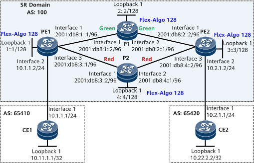
Networking Requirements
PE1, the Ps, and PE2 are in the same AS and run IS-IS to implement IPv6 network connectivity.
PE1, the Ps, and PE2 are Level-1 devices that belong to IS-IS process 1.
It is required that a bidirectional SRv6 BE path be deployed between PE1 and PE2 to carry L3VPNv4 services. Service traffic needs to be forwarded over the specified link PE1-P1-PE2.
In this example, the affinity attributes are defined to meet the service requirements of vpna.
Precautions
When performing configurations, note the following:
After a VPN instance is bound to a PE interface connected to a CE, Layer 3 configurations on this interface are automatically deleted. Such configurations include IP address and routing protocol configurations, and must be added again if necessary.
In this example, the affinity attributes are used. To advertise the affinity attributes between devices, you need to run the ipv6 traffic-eng command to enable TE for the corresponding IS-IS process.
- In SRv6 Flex-Algo scenarios, locators must be configured on both PEs and Ps, and IS-IS SRv6 must be enabled using the segment-routing ipv6 locator locator-name command in the IS-IS view. Otherwise, SRv6 locator routes cannot be advertised, and PEs at both ends cannot learn locator routes from each other.
Configuration Roadmap
The configuration roadmap is as follows:
Enable IPv6 forwarding and configure an IPv6 address for each interface on PE1, P1, PE2, and P2.
Enable IS-IS, configure an IS-IS level, and specify a network entity title (NET) on PE1, P1, PE2, and P2.
- Configure Flex-Algo link attributes.
- Configure FADs.
- Enable IS-IS-based Flex-Algo advertisement and IS-IS TE.
Configure VPN instances on PE1 and PE2.
Establish an EBGP peer relationship between each PE and its connected CE.
Establish an MP-IBGP peer relationship between the PEs.
- Establish a Flex-Algo-based SRv6 BE path between the PEs.
Data Preparation
To complete the configuration, you need the following data:
IPv6 address of each interface on PE1, P1, PE2, and P2
IS-IS process IDs of PE1, P1, PE2, and P2
IS-IS levels of PE1, P1, PE2, and P2
VPN instance names, RDs, and RTs on PE1 and PE2
Procedure
- Enable IPv6 forwarding and configure an IPv6 address for each interface. The following example uses the configuration of PE1. The configurations of other devices are similar to the configuration of PE1. For configuration details, see Configuration Files in this section.
<HUAWEI> system-view
[~HUAWEI] sysname PE1
[*HUAWEI] commit
[~PE1] interface gigabitethernet 0/1/0
[~PE1-GigabitEthernet0/1/0] ipv6 enable
[*PE1-GigabitEthernet0/1/0] ipv6 address 2001:db8:1::1 96
[*PE1-GigabitEthernet0/1/0] quit
[*PE1] interface gigabitethernet 0/1/16
[*PE1-GigabitEthernet0/1/16] ipv6 enable
[*PE1-GigabitEthernet0/1/16] ipv6 address 2001:db8:3::1 96
[*PE1-GigabitEthernet0/1/16] quit
[*PE1] interface LoopBack 1
[*PE1-LoopBack1] ipv6 enable
[*PE1-LoopBack1] ipv6 address 1::1 128
[*PE1-LoopBack1] quit
[*PE1] commit
- Configure IS-IS.
# Configure PE1.
[~PE1] isis 1
[*PE1-isis-1] is-level level-1
[*PE1-isis-1] cost-style wide
[*PE1-isis-1] network-entity 10.0000.0000.0001.00
[*PE1-isis-1] ipv6 enable topology ipv6
[*PE1-isis-1] quit
[*PE1] interface gigabitethernet 0/1/0
[*PE1-GigabitEthernet0/1/0] isis ipv6 enable 1
[*PE1-GigabitEthernet0/1/0] quit
[*PE1] interface gigabitethernet 0/1/16
[*PE1-GigabitEthernet0/1/16] isis ipv6 enable 1
[*PE1-GigabitEthernet0/1/16] quit
[*PE1] interface loopback1
[*PE1-LoopBack1] isis ipv6 enable 1
[*PE1-LoopBack1] commit
[~PE1-LoopBack1] quit
# Configure P1.
[~P1] isis 1
[*P1-isis-1] is-level level-1
[*P1-isis-1] cost-style wide
[*P1-isis-1] network-entity 10.0000.0000.0002.00
[*P1-isis-1] ipv6 enable topology ipv6
[*P1-isis-1] quit
[*P1] interface gigabitethernet 0/1/0
[*P1-GigabitEthernet0/1/0] isis ipv6 enable 1
[*P1-GigabitEthernet0/1/0] quit
[*P1] interface gigabitethernet 0/1/8
[*P1-GigabitEthernet0/1/8] isis ipv6 enable 1
[*P1-GigabitEthernet0/1/8] quit
[*P1] interface loopback1
[*P1-LoopBack1] isis ipv6 enable 1
[*P1-LoopBack1] commit
[~P1-LoopBack1] quit
# Configure PE2.
[~PE2] isis 1
[*PE2-isis-1] is-level level-1
[*PE2-isis-1] cost-style wide
[*PE2-isis-1] network-entity 10.0000.0000.0003.00
[*PE2-isis-1] ipv6 enable topology ipv6
[*PE2-isis-1] quit
[*PE2] interface gigabitethernet 0/1/0
[*PE2-GigabitEthernet0/1/0] isis ipv6 enable 1
[*PE2-GigabitEthernet0/1/0] quit
[*PE2] interface gigabitethernet 0/1/16
[*PE2-GigabitEthernet0/1/16] isis ipv6 enable 1
[*PE2-GigabitEthernet0/1/16] quit
[*PE2] interface loopback1
[*PE2-LoopBack1] isis ipv6 enable 1
[*PE2-LoopBack1] commit
[~PE2-LoopBack1] quit
# Configure P2.
[~P2] isis 1
[*P2-isis-1] is-level level-1
[*P2-isis-1] cost-style wide
[*P2-isis-1] network-entity 10.0000.0000.0004.00
[*P2-isis-1] ipv6 enable topology ipv6
[*P2-isis-1] quit
[*P2] interface gigabitethernet 0/1/0
[*P2-GigabitEthernet0/1/0] isis ipv6 enable 1
[*P2-GigabitEthernet0/1/0] quit
[*P2] interface gigabitethernet 0/1/8
[*P2-GigabitEthernet0/1/8] isis ipv6 enable 1
[*P2-GigabitEthernet0/1/8] quit
[*P2] interface loopback1
[*P2-LoopBack1] isis ipv6 enable 1
[*P2-LoopBack1] commit
[~P2-LoopBack1] quit
After the configuration is complete, perform the following operations to check whether IS-IS is successfully configured:
# Display IS-IS neighbor information. The following example uses the command output on PE1.
[~PE1] display isis peer

                          Peer information for ISIS(1)

  System Id     Interface          Circuit Id        State HoldTime Type     PRI
--------------------------------------------------------------------------------
0000.0000.0002* GE0/1/0            0000.0000.0002.01  Up   6s       L1       64
0000.0000.0004* GE0/1/16            0000.0000.0004.01  Up   9s       L1       64

Total Peer(s): 2
# Display IS-IS routing table information. The following example uses the command output on PE1.
[~PE1] display isis route
                         Route information for ISIS(1)
                         -----------------------------

                        ISIS(1) Level-1 Forwarding Table
                        --------------------------------
 IPV6 Dest.     ExitInterface      NextHop                    Cost     Flags
--------------------------------------------------------------------------------
1::1/128        Loop1              Direct                     0        D/-/L/-
2::2/128        GE0/1/0            FE80::3A5D:67FF:FE31:307   10       A/-/-/-
3::3/128        GE0/1/0            FE80::3A5D:67FF:FE31:307   20       A/-/-/-
                GE0/1/16            FE80::3A5D:67FF:FE41:305
4::4/128        GE0/1/16            FE80::3A5D:67FF:FE41:305   10       A/-/-/-
2001:DB8:1::/96 GE0/1/0            Direct                     10       D/-/L/-
2001:DB8:2::/96 GE0/1/0            FE80::3A5D:67FF:FE31:307   20       A/-/-/-
2001:DB8:3::/96 GE0/1/16            Direct                     10       D/-/L/-
2001:DB8:4::/96 GE0/1/16            FE80::3A5D:67FF:FE41:305   20       A/-/-/-
     Flags: D-Direct, A-Added to URT, L-Advertised in LSPs, S-IGP Shortcut,
            U-Up/Down Bit Set, LP-Local Prefix-Sid
     Protect Type: L-Link Protect, N-Node Protect
- Configure Flex-Algo link attributes.
# Configure PE1.
[~PE1] te attribute enable
[*PE1] path-constraint affinity-mapping
[*PE1-pc-af-map] attribute green bit-sequence 1
[*PE1-pc-af-map] attribute red bit-sequence 9
[*PE1-pc-af-map] quit
[*PE1] interface gigabitethernet0/1/0
[*PE1-GigabitEthernet0/1/0] te link-attribute-application flex-algo
[*PE1-GigabitEthernet0/1/0-te-link-attribute-application] link administrative group name green
[*PE1-GigabitEthernet0/1/0-te-link-attribute-application] quit
[*PE1-GigabitEthernet0/1/0] quit
[*PE1] interface gigabitethernet0/1/16
[*PE1-GigabitEthernet0/1/16] te link-attribute-application flex-algo
[*PE1-GigabitEthernet0/1/16-te-link-attribute-application] link administrative group name red
[*PE1-GigabitEthernet0/1/16-te-link-attribute-application] quit
[*PE1-GigabitEthernet0/1/16] quit
[*PE1] commit
# Configure P1.
[~P1] te attribute enable
[*P1] path-constraint affinity-mapping
[*P1-pc-af-map] attribute green bit-sequence 1
[*P1-pc-af-map] attribute red bit-sequence 9
[*P1-pc-af-map] quit
[*P1] interface gigabitethernet0/1/0
[*P1-GigabitEthernet0/1/0] te link-attribute-application flex-algo
[*P1-GigabitEthernet0/1/0-te-link-attribute-application] link administrative group name green
[*P1-GigabitEthernet0/1/0-te-link-attribute-application] quit
[*P1-GigabitEthernet0/1/0] quit
[*P1] interface gigabitethernet0/1/8
[*P1-GigabitEthernet0/1/8] te link-attribute-application flex-algo
[*P1-GigabitEthernet0/1/8-te-link-attribute-application] link administrative group name green
[*P1-GigabitEthernet0/1/8-te-link-attribute-application] quit
[*P1-GigabitEthernet0/1/8] quit
[*P1] commit
# Configure PE2.
[~PE2] te attribute enable
[*PE2] path-constraint affinity-mapping
[*PE2-pc-af-map] attribute green bit-sequence 1
[*PE2-pc-af-map] attribute red bit-sequence 9
[*PE2-pc-af-map] quit
[*PE2] interface gigabitethernet0/1/0
[*PE2-GigabitEthernet0/1/0] te link-attribute-application flex-algo
[*PE2-GigabitEthernet0/1/0-te-link-attribute-application] link administrative group name green
[*PE2-GigabitEthernet0/1/0-te-link-attribute-application] quit
[*PE2-GigabitEthernet0/1/0] quit
[*PE2] interface gigabitethernet0/1/16
[*PE2-GigabitEthernet0/1/16] te link-attribute-application flex-algo
[*PE2-GigabitEthernet0/1/16-te-link-attribute-application] link administrative group name red
[*PE2-GigabitEthernet0/1/16-te-link-attribute-application] quit
[*PE2-GigabitEthernet0/1/16] quit
[*PE2] commit
# Configure P2.
[~P2] te attribute enable
[*P2] path-constraint affinity-mapping
[*P2-pc-af-map] attribute green bit-sequence 1
[*P2-pc-af-map] attribute red bit-sequence 9
[*P2-pc-af-map] quit
[*P2] interface gigabitethernet0/1/0
[*P2-GigabitEthernet0/1/0] te link-attribute-application flex-algo
[*P2-GigabitEthernet0/1/0-te-link-attribute-application] link administrative group name red
[*P2-GigabitEthernet0/1/0-te-link-attribute-application] quit
[*P2-GigabitEthernet0/1/0] quit
[*P2] interface gigabitethernet0/1/8
[*P2-GigabitEthernet0/1/8] te link-attribute-application flex-algo
[*P2-GigabitEthernet0/1/8-te-link-attribute-application] link administrative group name red
[*P2-GigabitEthernet0/1/8-te-link-attribute-application] quit
[*P2-GigabitEthernet0/1/8] quit
[*P2] commit
- Configure FADs.
You can select one or two devices in the same IGP domain to configure FADs. To improve reliability, you are advised to select two devices.
# Configure PE1.
[~PE1] flex-algo identifier 128
[*PE1-flex-algo-128] priority 100
[*PE1-flex-algo-128] affinity include-all green
[*PE1-flex-algo-128] quit
[*PE1] commit
# Configure PE2.
[~PE2] flex-algo identifier 128
[*PE2-flex-algo-128] priority 100
[*PE2-flex-algo-128] affinity include-all green
[*PE2-flex-algo-128] quit
[*PE2] commit
- Enable IS-IS-based Flex-Algo advertisement and IS-IS TE.
# Configure PE1.
[~PE1] isis 1
[*PE1-isis-1] flex-algo 128 level-1
[*PE1-isis-1] ipv6 traffic-eng level-1
[*PE1-isis-1] quit
[*PE1] commit
# Configure P1.
[~P1] isis 1
[*P1-isis-1] flex-algo 128 level-1
[*P1-isis-1] ipv6 traffic-eng level-1
[*P1-isis-1] quit
[*P1] commit
# Configure PE2.
[~PE2] isis 1
[*PE2-isis-1] flex-algo 128 level-1
[*PE2-isis-1] ipv6 traffic-eng level-1
[*PE2-isis-1] quit
[*PE2] commit
# Configure P2.
[~P2] isis 1
[*P2-isis-1] flex-algo 128 level-1
[*P2-isis-1] ipv6 traffic-eng level-1
[*P2-isis-1] quit
[*P2] commit
- Configure a VPN instance on each PE, enable the IPv4 address family for the instance, and bind the interface that connects each PE to a CE to the VPN instance on that PE.
# Configure PE1.
[~PE1] ip vpn-instance vpna
[*PE1-vpn-instance-vpna] ipv4-family
[*PE1-vpn-instance-vpna-af-ipv4] route-distinguisher 100:1
[*PE1-vpn-instance-vpna-af-ipv4] vpn-target 111:1 both
[*PE1-vpn-instance-vpna-af-ipv4] quit
[*PE1-vpn-instance-vpna] quit
[*PE1] interface gigabitethernet 0/1/8
[*PE1-GigabitEthernet0/1/8] ip binding vpn-instance vpna
[*PE1-GigabitEthernet0/1/8] ip address 10.1.1.2 24
[*PE1-GigabitEthernet0/1/8] quit
[*PE1] commit
# Configure PE2.
[~PE2] ip vpn-instance vpna
[*PE2-vpn-instance-vpna] ipv4-family
[*PE2-vpn-instance-vpna-af-ipv4] route-distinguisher 200:1
[*PE2-vpn-instance-vpna-af-ipv4] vpn-target 111:1 both
[*PE2-vpn-instance-vpna-af-ipv4] quit
[*PE2-vpn-instance-vpna] quit
[*PE2] interface gigabitethernet 0/1/8
[*PE2-GigabitEthernet0/1/8] ip binding vpn-instance vpna
[*PE2-GigabitEthernet0/1/8] ip address 10.2.1.2 24
[*PE2-GigabitEthernet0/1/8] quit
[*PE2] commit
# Assign an IP address to each interface on the CEs, as shown in Figure 1. For configuration details, see Configuration Files in this section.
After the configuration is complete, run the display ip vpn-instance verbose command on the PEs to check VPN instance configurations. Check that each PE can successfully ping its connected CE.

If a PE has multiple interfaces bound to the same VPN instance, you need to specify a source IP address when running the ping -vpn-instance vpn-instance-name -a source-ip-address dest-ip-address command to ping the CE connected to the remote PE. Otherwise, the ping operation may fail.
- Establish an EBGP peer relationship between each PE and its connected CE.
# Configure CE1.
[~CE1] interface loopback 1
[*CE1-LoopBack1] ip address 10.11.1.1 32
[*CE1-LoopBack1] quit
[*CE1] bgp 65410
[*CE1-bgp] peer 10.1.1.2 as-number 100
[*CE1-bgp] network 10.11.1.1 32
[*CE1-bgp] quit
[*CE1] commit
# Configure PE1.
[~PE1] bgp 100
[*PE1-bgp] router-id 1.1.1.1
[*PE1-bgp] ipv4-family vpn-instance vpna
[*PE1-bgp-vpna] peer 10.1.1.1 as-number 65410
[*PE1-bgp-vpna] import-route direct
[*PE1-bgp-vpna] commit
[~PE1-bgp-vpna] quit
[~PE1-bgp] quit
# Configure CE2.
[~CE2] interface loopback 1
[*CE2-LoopBack1] ip address 10.22.2.2 32
[*CE2-LoopBack1] quit
[*CE2] bgp 65420
[*CE2-bgp] peer 10.2.1.2 as-number 100
[*CE2-bgp] network 10.22.2.2 32
[*CE2-bgp] quit
[*CE2] commit
# Configure PE2.
[~PE2] bgp 100
[*PE2-bgp] router-id 2.2.2.2
[*PE2-bgp] ipv4-family vpn-instance vpna
[*PE2-bgp-vpna] peer 10.2.1.1 as-number 65420
[*PE2-bgp-vpna] import-route direct
[*PE2-bgp-vpna] commit
[~PE2-bgp-vpna] quit
[~PE2-bgp] quit
After the configuration is complete, run the display bgp vpnv4 vpn-instance peer command on the PEs to check whether BGP peer relationships have been established between the PEs and CEs. If the Established state is displayed in the command output, the BGP peer relationships have been established successfully.
The following example uses the command output on PE1 to show that a BGP peer relationship has been established between PE1 and CE1.
[~PE1] display bgp vpnv4 vpn-instance vpna peer BGP local router ID : 1.1.1.1 Local AS number : 100 VPN-Instance vpna, Router ID 1.1.1.1: Total number of peers : 1 Peers in established state : 1 Peer V AS MsgRcvd MsgSent OutQ Up/Down State PrefRcv 10.1.1.1 4 65410 147 148 0 02:05:47 Established 1 - Establish an MP-IBGP peer relationship between the PEs.
# Configure PE1.
[~PE1] bgp 100
[~PE1-bgp] peer 3::3 as-number 100
[*PE1-bgp] peer 3::3 connect-interface loopback 1
[*PE1-bgp] ipv4-family vpnv4
[*PE1-bgp-af-vpnv4] peer 3::3 enable
[*PE1-bgp-af-vpnv4] commit
[~PE1-bgp-af-vpnv4] quit
[~PE1-bgp] quit
# Configure PE2.
[~PE2] bgp 100
[~PE2-bgp] peer 1::1 as-number 100
[*PE2-bgp] peer 1::1 connect-interface loopback 1
[*PE2-bgp] ipv4-family vpnv4
[*PE2-bgp-af-vpnv4] peer 1::1 enable
[*PE2-bgp-af-vpnv4] commit
[~PE2-bgp-af-vpnv4] quit
[~PE2-bgp] quit
After the configuration is complete, run the display bgp vpnv4 all peer command on the PEs to check whether a BGP peer relationship has been established between the PEs. If the Established state is displayed in the command output, the BGP peer relationship has been established successfully. The following example uses the command output on PE1.
[~PE1] display bgp vpnv4 all peer

 BGP local router ID : 1.1.1.1
 Local AS number : 100
 Total number of peers : 2                 Peers in established state : 2

  Peer                             V          AS  MsgRcvd  MsgSent  OutQ  Up/Down       State  PrefRcv
  3::3                             4         100      149      149     0 02:06:22 Established        2

  Peer of IPv4-family for vpn instance :

  VPN-Instance vpna, Router ID 1.1.1.1:
  Peer                             V          AS  MsgRcvd  MsgSent  OutQ  Up/Down       State  PrefRcv
  10.1.1.1                         4       65410      150      151     0 02:08:04 Established        1
- Establish a Flex-Algo-based SRv6 BE path between the PEs.
An End.DT4 SID can be either dynamically allocated through BGP or manually configured. If a dynamically allocated SID and a manually configured SID both exist, the latter takes effect. If dynamic End.DT4 SID allocation through BGP has been enabled using the segment-routing ipv6 locator locator-name command, you do not need to run the opcode func-opcode end-dt4 vpn-instance vpn-instance-name command to configure a static SID opcode.
In this example, SIDs are dynamically allocated through BGP.
# Configure PE1.
[~PE1] segment-routing ipv6
[*PE1-segment-routing-ipv6] encapsulation source-address 1::1
[*PE1-segment-routing-ipv6] locator as1 ipv6-prefix 10:: 64 static 32 flex-algo 128
[*PE1-segment-routing-ipv6-locator] quit
[*PE1-segment-routing-ipv6] quit
[*PE1] bgp 100
[*PE1-bgp] ipv4-family vpnv4
[*PE1-bgp-af-vpnv4] peer 3::3 prefix-sid
[*PE1-bgp-af-vpnv4] quit
[*PE1-bgp] ipv4-family vpn-instance vpna
[*PE1-bgp-vpna] segment-routing ipv6 best-effort
[*PE1-bgp-vpna] segment-routing ipv6 locator as1
[*PE1-bgp-vpna] quit
[*PE1-bgp] quit
[*PE1] isis 1
[*PE1-isis-1] segment-routing ipv6 locator as1
[*PE1-isis-1] commit
[~PE1-isis-1] quit
# Configure PE2.
[~PE2] segment-routing ipv6
[*PE2-segment-routing-ipv6] encapsulation source-address 3::3
[*PE2-segment-routing-ipv6] locator as1 ipv6-prefix 30:: 64 static 32 flex-algo 128
[*PE2-segment-routing-ipv6-locator] quit
[*PE2-segment-routing-ipv6] quit
[*PE2] bgp 100
[*PE2-bgp] ipv4-family vpnv4
[*PE2-bgp-af-vpnv4] peer 1::1 prefix-sid
[*PE2-bgp-af-vpnv4] quit
[*PE2-bgp] ipv4-family vpn-instance vpna
[*PE2-bgp-vpna] segment-routing ipv6 best-effort
[*PE2-bgp-vpna] segment-routing ipv6 locator as1
[*PE2-bgp-vpna] quit
[*PE2-bgp] quit
[*PE2] isis 1
[*PE2-isis-1] segment-routing ipv6 locator as1
[*PE2-isis-1] commit
[~PE2-isis-1] quit
# Configure P1.
[~P1] segment-routing ipv6
[*P1-segment-routing-ipv6] locator as1 ipv6-prefix 20:: 64 static 32 flex-algo 128
[*P1-segment-routing-ipv6-locator] quit
[*P1-segment-routing-ipv6] quit
[*P1] isis 1
[*P1-isis-1] segment-routing ipv6 locator as1
[*P1-isis-1] commit
[~P1-isis-1] quit
# Configure P2.
[~P2] segment-routing ipv6
[*P2-segment-routing-ipv6] locator as1 ipv6-prefix 40:: 64 static 32 flex-algo 128
[*P2-segment-routing-ipv6-locator] quit
[*P2-segment-routing-ipv6] quit
[*P2] isis 1
[*P2-isis-1] segment-routing ipv6 locator as1
[*P2-isis-1] commit
[~P2-isis-1] quit
- Verify the configuration.
Run the display segment-routing ipv6 locator [ locator-name ] verbose command to check SRv6 locator information. The following example uses the command output on PE1.
[~PE1] display segment-routing ipv6 locator verbose
                        Locator Configuration Table
                        ---------------------------

LocatorName   : as1                                       LocatorID     : 2
IPv6Prefix    : 10::                                      PrefixLength  : 64
Block         : --                                        BlockLength   : 0
NodeID        : --                                        NodeIdLength  : 0
ComprStaticLen: 0                                         StaticLength  : 32
ArgsLength    : 0                                         Reference     : 0
AutoCSIDPoolID: 0                                         ComprDynLength: 0
Algorithm     : 128
AutoCSIDBegin : --
AutoCSIDEnd   : --
StaticCSIDBegin: --
StaticCSIDEnd : --
AutoSIDPoolID : 8193                                      DynLength     : 32
AutoSIDBegin  : 10::1:0:0
AutoSIDEnd    : 10::FFFF:FFFF:FFFF:FFFF
StaticSIDBegin: 10::1
StaticSIDEnd  : 10::FFFF:FFFF

Total Locator(s): 1
Run the display segment-routing ipv6 local-sid end-dt4 forwarding command to check information about the SRv6 local SID table. The following example uses the command output on PE1.
[~PE1] display segment-routing ipv6 local-sid end-dt4 forwarding

                    My Local-SID End.DT4 Forwarding Table
                    -------------------------------------

SID        : 10::1:0:20/128                               FuncType : End.DT4
VPN Name   : vpna                                         VPN ID   : 3
LocatorName: as1                                          LocatorID: 1

Total SID(s): 1
Run the display bgp vpnv4 all routing-table command on each PE to check BGP VPNv4 routing information. The following example uses the command output on PE1.
[~PE1] display bgp vpnv4 all routing-table

 BGP Local router ID is 1.1.1.1
 Status codes: * - valid, > - best, d - damped, x - best external, a - add path,
               h - history,  i - internal, s - suppressed, S - Stale
               Origin : i - IGP, e - EGP, ? - incomplete
 RPKI validation codes: V - valid, I - invalid, N - not-found


 Total number of routes from all PE: 6
 Route Distinguisher: 100:1


        Network            NextHop                       MED        LocPrf    PrefVal Path/Ogn

 *>     10.1.1.0/24        0.0.0.0                        0                     0       ?
 *>     10.1.1.1/32        0.0.0.0                        0                     0       ?
 *>     10.11.1.1/32       10.1.1.1                       0                     0      65410i
 *>     127.0.0.0/8        0.0.0.0                        0                     0       ?
 Route Distinguisher: 200:1


        Network            NextHop                       MED        LocPrf    PrefVal Path/Ogn

 *>i    10.2.1.0/24        3::3                           0          100        0       ?
 *>i    10.22.2.2/32       3::3                           0          100        0      65420i

 VPN-Instance vpna, Router ID 1.1.1.1:

 Total Number of Routes: 6
        Network            NextHop                       MED        LocPrf    PrefVal Path/Ogn

 *>     10.1.1.0/24        0.0.0.0                        0                     0       ?
 *>     10.1.1.1/32        0.0.0.0                        0                     0       ?
 *>i    10.2.1.0/24        3::3                           0          100        0       ?
 *>     10.11.1.1/32       10.1.1.1                       0                     0      65410i
 *>i    10.22.2.2/32       3::3                           0          100        0      65420i
 *>     127.0.0.0/8        0.0.0.0                        0                     0       ?
Run the display ip routing-table vpn-instance vpna command on PEs to check VPN routing table information. The following example uses the command output on PE1.
[~PE1] display ip routing-table vpn-instance vpna
Route Flags: R - relay, D - download to fib, T - to vpn-instance, B - black hole route
------------------------------------------------------------------------------
Routing Table : vpna
         Destinations : 8        Routes : 8

Destination/Mask    Proto   Pre  Cost        Flags NextHop         Interface

       10.1.1.0/24  Direct  0    0             D   10.1.1.2        GigabitEthernet0/1/8
       10.1.1.2/32  Direct  0    0             D   127.0.0.1       GigabitEthernet0/1/8
     10.1.1.255/32  Direct  0    0             D   127.0.0.1       GigabitEthernet0/1/8
       10.2.1.0/24  IBGP    255  0             RD  30::1:0:20      SRv6 BE
      10.11.1.1/32  EBGP    255  0             RD  10.1.1.1        GigabitEthernet0/1/8
      10.22.2.2/32  IBGP    255  0             RD  30::1:0:20      SRv6 BE
      127.0.0.0/8   Direct  0    0             D   127.0.0.1       InLoopBack0
255.255.255.255/32  Direct  0    0             D   127.0.0.1       InLoopBack0
Run the display ip routing-table vpn-instance vpna ip-address verbose command on PEs to check detailed VPN routing table information. The following example uses the command output on PE1.
[~PE1] display ip routing-table vpn-instance vpna 10.22.2.2 verbose
Route Flags: R - relay, D - download to fib, T - to vpn-instance, B - black hole route
------------------------------------------------------------------------------
Routing Table : vpna
Summary Count : 1

Destination: 10.22.2.2/32
     Protocol: IBGP               Process ID: 0
   Preference: 255                      Cost: 0
      NextHop: 30::1:0:20          Neighbour: 3::3
        State: Active Adv Relied         Age: 00h03m06s
          Tag: 0                    Priority: low
        Label: 3                     QoSInfo: 0x0
   IndirectID: 0x10000C3            Instance:
 RelayNextHop: 30::1:0:20          Interface: SRv6 BE
     TunnelID: 0x0                     Flags: RD
Check that CEs belonging to the same VPN instance can ping each other. The following example uses the command output on CE1.
[~CE1] ping -a 10.11.1.1 10.22.2.2
  PING 10.22.2.2: 56  data bytes, press CTRL_C to break
    Reply from 10.22.2.2: bytes=56 Sequence=1 ttl=253 time=4 ms
    Reply from 10.22.2.2: bytes=56 Sequence=2 ttl=253 time=3 ms
    Reply from 10.22.2.2: bytes=56 Sequence=3 ttl=253 time=3 ms
    Reply from 10.22.2.2: bytes=56 Sequence=4 ttl=253 time=3 ms
    Reply from 10.22.2.2: bytes=56 Sequence=5 ttl=253 time=3 ms

  --- 10.22.2.2 ping statistics ---
    5 packet(s) transmitted
    5 packet(s) received
    0.00% packet loss
    round-trip min/avg/max = 3/115/567 ms
Configuration Files
PE1 configuration file
#
sysname PE1
#
ip vpn-instance vpna
 ipv4-family
  route-distinguisher 100:1
  apply-label per-instance
  vpn-target 111:1 export-extcommunity
  vpn-target 111:1 import-extcommunity
#
te attribute enable
#
path-constraint affinity-mapping
 attribute green bit-sequence 1
 attribute red bit-sequence 9
#
flex-algo identifier 128
 priority 100
 affinity include-all green
#
segment-routing ipv6
 encapsulation source-address 1::1
 locator as1 ipv6-prefix 10:: 64 static 32 flex-algo 128
#
isis 1
 is-level level-1
 cost-style wide
 network-entity 10.0000.0000.0001.00
 flex-algo 128 level-1
 #
 ipv6 enable topology ipv6
 ipv6 traffic-eng level-1
 segment-routing ipv6 locator as1
 #
#
interface GigabitEthernet0/1/0
 undo shutdown
 ipv6 enable
 ipv6 address 2001:DB8:1::1/96
 isis ipv6 enable 1
 te link-attribute-application flex-algo
  link administrative group name red
#
interface GigabitEthernet0/1/8
 undo shutdown
 ip binding vpn-instance vpna
 ip address 10.1.1.2 255.255.255.0
#
interface GigabitEthernet0/1/16
 undo shutdown
 ipv6 enable
 ipv6 address 2001:DB8:3::1/96
 isis ipv6 enable 1
 te link-attribute-application flex-algo
  link administrative group name green
#
interface LoopBack1
 ipv6 enable
 ipv6 address 1::1/128
 isis ipv6 enable 1
#
bgp 100
 router-id 1.1.1.1
 peer 3::3 as-number 100
 peer 3::3 connect-interface LoopBack1
 #
 ipv4-family unicast
  undo synchronization
 #
 ipv6-family unicast
  undo synchronization
 #
 ipv4-family vpnv4
  policy vpn-target
  peer 3::3 enable
  peer 3::3 prefix-sid
 #
 ipv4-family vpn-instance vpna
  import-route direct
  segment-routing ipv6 locator as1
  segment-routing ipv6 best-effort
  peer 10.1.1.1 as-number 65410
#
return
P1 configuration file
#
sysname P1
#
te attribute enable
#
path-constraint affinity-mapping
 attribute green bit-sequence 1
 attribute red bit-sequence 9
#
segment-routing ipv6
 locator as1 ipv6-prefix 20:: 64 static 32 flex-algo 128
#
isis 1
 is-level level-1
 cost-style wide
 network-entity 10.0000.0000.0002.00
 flex-algo 128 level-1
 #
 ipv6 enable topology ipv6
 ipv6 traffic-eng level-1
 segment-routing ipv6 locator as1
 #
#
interface GigabitEthernet0/1/0
 undo shutdown
 ipv6 enable
 ipv6 address 2001:DB8:1::2/96
 isis ipv6 enable 1
 te link-attribute-application flex-algo
  link administrative group name green
#
interface GigabitEthernet0/1/8
 undo shutdown
 ipv6 enable
 ipv6 address 2001:DB8:2::1/96
 isis ipv6 enable 1
 te link-attribute-application flex-algo
  link administrative group name green
#
interface LoopBack1
 ipv6 enable
 ipv6 address 2::2/128
 isis ipv6 enable 1
#
return
PE2 configuration file
#
sysname PE2
#
ip vpn-instance vpna
 ipv4-family
  route-distinguisher 200:1
  apply-label per-instance
  vpn-target 111:1 export-extcommunity
  vpn-target 111:1 import-extcommunity
#
te attribute enable
#
path-constraint affinity-mapping
 attribute green bit-sequence 1
 attribute red bit-sequence 9
#
flex-algo identifier 128
 priority 100
 affinity include-all green
#
segment-routing ipv6
 encapsulation source-address 3::3
 locator as1 ipv6-prefix 30:: 64 static 32 flex-algo 128
#
isis 1
 is-level level-1
 cost-style wide
 network-entity 10.0000.0000.0003.00
 flex-algo 128 level-1
 #
 ipv6 enable topology ipv6
 ipv6 traffic-eng level-1
 segment-routing ipv6 locator as1
 #
#
interface GigabitEthernet0/1/0
 undo shutdown
 ipv6 enable
 ipv6 address 2001:DB8:2::2/96
 isis ipv6 enable 1
 te link-attribute-application flex-algo
  link administrative group name red
#
interface GigabitEthernet0/1/8
 undo shutdown
 ip binding vpn-instance vpna
 ip address 10.2.1.2 255.255.255.0
#
interface GigabitEthernet0/1/16
 undo shutdown
 ipv6 enable
 ipv6 address 2001:DB8:4::2/96
 isis ipv6 enable 1
 te link-attribute-application flex-algo
  link administrative group name green
#
interface LoopBack1
 ipv6 enable
 ipv6 address 3::3/128
 isis ipv6 enable 1
#
bgp 100
 router-id 2.2.2.2
 peer 1::1 as-number 100
 peer 1::1 connect-interface LoopBack1
 #
 ipv4-family unicast
  undo synchronization
 #
 ipv4-family vpnv4
  policy vpn-target
  peer 1::1 enable
  peer 1::1 prefix-sid
 #
 ipv4-family vpn-instance vpna
  import-route direct
  segment-routing ipv6 locator as1
  segment-routing ipv6 best-effort
  peer 10.2.1.1 as-number 65420
#
return
P2 configuration file
#
sysname P2
#
te attribute enable
#
path-constraint affinity-mapping
 attribute green bit-sequence 1
 attribute red bit-sequence 9
#
segment-routing ipv6
 locator as1 ipv6-prefix 40:: 64 static 32 flex-algo 128
#
isis 1
 is-level level-1
 cost-style wide
 network-entity 10.0000.0000.0004.00
 flex-algo 128 level-1
 #
 ipv6 enable topology ipv6
 ipv6 traffic-eng level-1
 segment-routing ipv6 locator as1
 #
#
interface GigabitEthernet0/1/0
 undo shutdown
 ipv6 enable
 ipv6 address 2001:db8:3::2/96
 isis ipv6 enable 1
 te link-attribute-application flex-algo
  link administrative group name red
#
interface GigabitEthernet0/1/8
 undo shutdown
 ipv6 enable
 ipv6 address 2001:db8:4::1/96
 isis ipv6 enable 1
 te link-attribute-application flex-algo
  link administrative group name red
#
interface LoopBack1
 ipv6 enable
 ipv6 address 4::4/128
 isis ipv6 enable 1
#
return
CE1 configuration file
#
sysname CE1
#
interface GigabitEthernet0/1/0
 undo shutdown
 ip address 10.1.1.1 255.255.255.0
#
interface LoopBack1
 ip address 10.11.1.1 255.255.255.255
#
bgp 65410
 peer 10.1.1.2 as-number 100
 network 10.11.1.1 255.255.255.255
 #
 ipv4-family unicast
  peer 10.1.1.2 enable
#
return
CE2 configuration file
#
sysname CE2
#
interface GigabitEthernet0/1/0
 undo shutdown
 ip address 10.2.1.1 255.255.255.0
#
interface LoopBack1
 ip address 10.22.2.2 255.255.255.255
#
bgp 65420
 peer 10.2.1.2 as-number 100
 network 10.22.2.2 255.255.255.255
 #
 ipv4-family unicast
  peer 10.2.1.2 enable
#
return