Configuring SRv6 Egress Protection
This section describes how to configure SRv6 egress protection to enhance SRv6 network reliability.
Pre-configuration Tasks
Before configuring SRv6 egress protection, configure an IGP to implement network layer connectivity
Context
Services that recurse to an SRv6 TE Policy must be strictly forwarded through the path defined using the segment lists in the SRv6 TE Policy. In addition, given that the egress of the SRv6 TE Policy is fixed, service forwarding may fail if a single point of failure occurs on the egress. To prevent this problem, configure egress protection for the SRv6 TE Policy.
- Locators 2001:DB8:A1::/64 and 2001:DB8:A2::/64 are configured on PE1 and PE2, respectively.
- An IPv6 VPNv4 peer relationship is established between PE3 and PE1, and another one is established between PE2 and PE1. A VPN instance VPN1 and SRv6 VPN SIDs are configured on both PE1 and PE2. In addition, IPv4 prefix SID advertisement is enabled on the two PEs.
- After receiving the VPN route advertised by CE2, PE1 encapsulates the route as a VPNv4 route and sends it to PE3. The route carries the VPN SID, RT, RD, and color information.
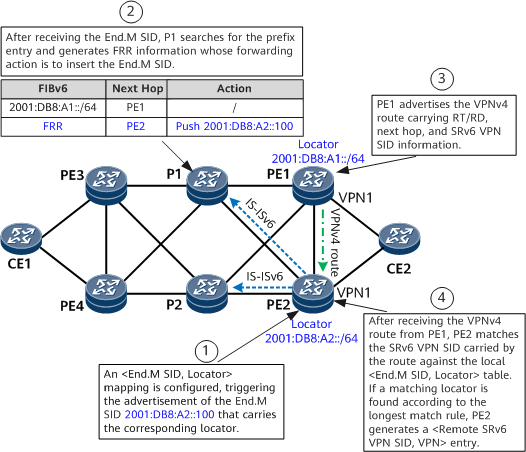
- An End.M SID is configured on PE2 to protect PE1, generating an <End.M SID, Locator> mapping entry (for example, <2001:DB8:A2::100, 2001:DB8:A1::>).
- PE2 propagates the End.M SID through an IGP and generates a local SID entry. After receiving the End.M SID, P1 generates an FRR entry in which the next-hop address is PE2 and the action is Push End.M SID. In addition, P1 generates a low-priority route that cannot be recursed.
- BGP subscribes to End.M SID configuration. After receiving the VPNv4 route from PE1, PE2 leaks the route into the routing table of VPN1 based on the RT, and matches the VPN SID carried by the route against the local <End.M SID, Locator> table. If a matching locator is found according to the longest match rule, PE2 generates a <Remote SRv6 VPN SID, VPN> entry.
- In normal situations, PE3 forwards traffic to the private network through the PE3-P1-PE1-CE2 path. If PE1 fails, P1 detects that the next hop PE1 is unreachable and switches traffic to the FRR path.
- P1 pushes the End.M SID into the packet header and forwards the packet to PE2. After parsing the received packet, PE2 obtains the End.M SID, queries the local SID table, and finds that the instruction specified by the End.M SID is to query the remote SRv6 VPN SID table. As instructed, PE2 queries the remote SRv6 VPN SID table based on the VPN SID in the packet and finds the corresponding VPN instance. PE2 then searches the VPN routing table and forwards the packet to CE2.
If PE1 fails, the peer relationship between PE2 and PE1 is interrupted. As a result, PE2 deletes the VPN route received from PE1, causing the <Remote SRv6 VPN SID, VPN> entry to be deleted on PE2. To prevent this, you can enable GR on PE2 and PE1 to maintain routes. Alternatively, enable delayed deletion (currently enabled by default) for the <Remote SRv6 VPN SID, VPN> entry on PE2.
Procedure
- Configure an SRv6 TE Policy along the PE3-P1-PE1 path.
For details about the configuration, see Configuring an SRv6 TE Policy (Manual Configuration) and Configuring an SRv6 TE Policy (Dynamic Delivery by a Controller).
- Configure services to recurse to the SRv6 TE Policy.
Supported service types include BGP L3VPN, EVPN L3VPN, EVPN VPWS, and EVPN VPLS. For details about the configuration, see Configuring SRv6 TE Policy Services.
- Configure protection on PE2.
- Configure IPv6 IS-IS FRR on each P.
- Enable IPv6 IS-IS TI-LFA FRR and microloop avoidance on the PEs and Ps.
Verifying the Configuration
After configuring SRv6 egress protection, verify the configuration.
Run the display segment-routing ipv6 local-sid end-m [ sid-value ] forwarding command to check information about local SIDs.
Run the display ipv6 routing-table vpn-instance vpn-instance-name command to check information about IPv6 VPN routes received from the remote end.
- Run the display bgp remote prefix-sid command to check the mappings between remote prefix SIDs, End.M locator routes, and local VPN instances.
