Configuring SRv6 Midpoint Protection
This section describes how to configure SRv6 midpoint protection to enhance SRv6 network reliability.
Pre-configuration Tasks
Configure an IGP to implement network layer connectivity.
- Configure an SRv6 TE Policy. For details, see Configuring an SRv6 TE Policy (Manual Configuration) and Configuring an SRv6 TE Policy (Dynamic Delivery by a Controller).
Context
In an SRv6 TE Policy scenario, strict node constraints may result in a TI-LFA FRR protection failure. To resolve this issue, a proxy forwarding node (a node upstream to the failed midpoint) takes over from the failed midpoint to complete the forwarding. Specifically, after detecting that the next-hop interface of the packet fails, the next-hop address is the destination address of the packet, and the SL value is greater than 0, the proxy forwarding node performs the End behavior on behalf of the midpoint. The behavior involves decrementing the SL value by 1, copying the next SID to the DA field in the outer IPv6 header, and then forwarding the packet according to the instruction bound to the SID. In this way, the failed midpoint is bypassed, achieving SRv6 midpoint protection.
- Node A forwards a packet to destination node F, with an SRv6 SRH instructing the packet to pass through the midpoint node D.
- If node D fails, node B detects that the next-hop interface of the received packet fails. It also learns that the next-hop address is the current destination address 4:: of the packet, and the SL value is greater than 0. In this case, node B functions as a proxy forwarding node, decrementing the SL value by 1 and copying the next SID 6:: to the DA field in the outer IPv6 header. Because the SL value is now 0, node B can remove the SRH and then search the corresponding table to forward the packet based on the destination address 6::.
- The primary next hop to the destination address 6:: is still node D. Because the SL value is 0 and node B is not the penultimate hop of the destination address, node B can no longer perform proxy forwarding. Instead, it switches the packet to a backup path according to the normal TI-LFA process, with the repair segment list on the backup path as <3::5>. As such, node B executes the H.Insert behavior, which involves encapsulating the segment list 3::5 into the packet, adding an SRH, and then forwarding the packet to node F over the backup path.
- After node A detects that node D fails and that IGP convergence is completed, it deletes the forwarding entry towards node D. Consequently, when node A searches the corresponding table based on 4::, it cannot find any matching route. In this case, node A needs to function as a proxy forwarding node to perform proxy forwarding, so it decrements the SL value by 1, copies the next SID 6:: to the outer IPv6 header, searches the corresponding table based on the destination address 6::, and then forwards the packet to node B accordingly. If node B has already converged, it forwards the packet to node F over the post-convergence shortest path; otherwise, it forwards the packet to node F over the backup path according to the TI-LFA process. In this way, the failed node D is bypassed.Figure 1 SRv6 midpoint protection
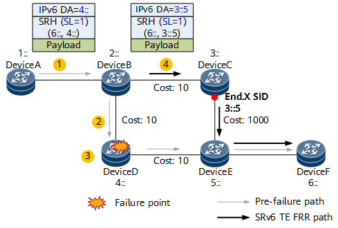

SRv6 midpoint protection uses the next SID to guide packet forwarding over the bypass path, thereby bypassing the failure point. This mechanism is similar to MPLS TE FRR, which enables traffic to bypass the failure point using a bypass LSP. SRv6 midpoint protection is therefore also called SRv6 TE FRR.
Procedure
- Run system-view
The system view is displayed.
- Run segment-routing ipv6
The SRv6 view is displayed.
- Run sr-te frr enable [ downgrade ]
SRv6 midpoint protection is enabled.
On a network with complex services, midpoint nodes are not fixed. Therefore, to improve network-wide reliability, you are advised to run the sr-te frr enable command on all nodes. However, for a network with simple services, you can run the sr-te frr enable command only on the upstream node of the protected node. For example, in the DeviceA-to-DeviceF direction shown in the preceding figure, to protect DeviceD, you can run the sr-te frr enable command on the upstream nodes (DeviceA and DeviceB) of DeviceD to enable midpoint protection.
The downgrade parameter is used to switch the protection mode to SRv6 BE, so that the innermost SID functions as the destination address for packet forwarding. In SRv6 SRH compression scenarios, the SID structure changes, and the SIDs in a segment list are associated with each other. Therefore, protection cannot be implemented simply by bypassing the faulty SID. In this case, the downgrade parameter must be configured.
- Run commit
The configuration is committed.