Configuring SRv6 SFC Reliability

This section describes how to configure SRv6 SFC reliability.

Prerequisites

Before configuring SRv6 SFC reliability, complete the following tasks:

Context

SFC services are forwarded in serial mode, meaning that a single link or node failure causes SFC service interruptions. To improve service reliability, SRv6 SFC provides backup link protection and bypass link protection.

  • In backup link protection, an SF is dual-homed to two SFFs, with one as the master and the other as the backup. The backup SFF is used to protect the primary SFF. If the primary SFF becomes unreachable, services are switched to the backup SFF for processing.
  • In bypass link protection, if an SF is unreachable, SFC traffic is switched to the bypass service path, without being processed by the current SF. An SFF usually discards SFC packets if an SF is unreachable. After bypass protection is configured, SFC packets can continue to be forwarded as follows:
    1. If no bypass SF is available for the current SF, SRv6 forwarding for SFC packets is implemented.
    2. If the current SF has a bypass SF to provide protection, SFC packets are switched to the bypass SF for processing.

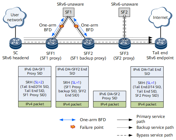
These protection schemes can be selected according to specific SFC networking scenarios. The following describes how to configure SRv6 SFC reliability, using the network shown in Figure 1 as an example. In Figure 1, SF1 is dual-homed to SFF1 and SFF2, and has a bypass SF – SF2.

Configuration roadmap:

  1. Configure a backup path for protection. Because SF1 is dual-homed to SFF1 and SFF2, SFF1 and SFF2 can provide protection for each other. Specifically, the same SF1 Proxy SID of the End.AS type needs to be configured on SFF1 and SFF2 to implement the anycast function. (For ease of description, the SF1 Proxy SID on SFF2 in Figure 1 is called SF1 Backup Proxy SID.) In addition, SFF1 and SFF2 need to be configured as peers of each other. The peer SID of SFF1 is the End SID of SFF2, and the peer SID of SFF2 is the End SID of SFF1.
  2. Configure a bypass service path by using SF2 to protect SF1. Specifically, configure a bypass protection SID for the SF1 Proxy SID, and configure the SF2 Proxy SID on SFF3.
  3. Configure one-arm BFD on SFF1 and SFF2 to detect SF1 reachability.
    • If one-arm BFD on SFF1 detects that SF1 is unreachable, the SFC traffic is switched to the backup service path. SFF1 replaces the original SRv6 segment list with the SF1 Proxy Backup SID and SFF2 End SID, and forwards the SFC packet to SFF2. After receiving the packet, SFF2 identifies that both the SF1 Proxy Backup SID and SFF2 End SID are its own SIDs. SFF2 then forwards the packet to SF1 based on the SF1 Proxy Backup SID.
    • SFC traffic is switched to SFF2 if one-arm BFD on SFF1 detects that SF1 is unreachable. If one-arm BFD on SFF2 also detects that SF1 is unreachable, the SFC traffic is switched to the bypass service path. SFF2 removes the SRH and searches the IPv6 routing table for packet forwarding, using the SF2 Proxy SID as the destination IPv6 address. After receiving the packet, SFF3 forwards the packet to SF2 based on the SF2 Proxy SID.
Figure 1 SFC scenario with a dual-homed SF that has a bypass SF

Procedure

  1. Configure SFF backup link protection.

    In this example, SF1 is dual-homed to SFF1 and SFF2, which can back up each other. The configurations of SFF1 and SFF2 are symmetrical. In an SF single-homing scenario, backup link protection cannot be implemented.

    1. Run system-view

      The system view is displayed.

    2. Run segment-routing ipv6

      SRv6 is enabled, and the SRv6 view is displayed.

    3. Run proxy peer-sid peersid

      A peer End SID is configured on the SFF.

      The peer SID on SFF1 is the End SID of SFF2, and the peer SID on SFF2 is the End SID of SFF1.

    4. Run locator locator-name [ ipv6-prefix ipv6-address prefix-length [ static static-length | args args-length ] * [ default ] ]

      An SRv6 locator is configured.

      To implement anycast protection, the configuration must be the same on SFF1 and SFF2.

    5. Run opcode func-opcode1 end-as

      A static End.AS SID's operation code (opcode) is configured, and the static SRv6 SFC proxy view is displayed.

      To implement anycast protection, the configuration must be the same on SFF1 and SFF2.

    6. Run backup-opcode func-opcode

      An opcode is configured for the static SRv6 SFC proxy backup SID.

      This opcode and locator form a backup SID.

      In the SF1 dual-homing scenario, the Backup SID on SFF1 is the SF1 Proxy SID on SFF2, and the Backup SID on SFF2 is the SF1 Proxy SID on SFF1. To implement anycast protection, the configuration must be the same on SFF1 and SFF2.

    7. Run commit

      The configuration is committed.

  2. Configure SFF bypass protection.
    1. Run system-view

      The system view is displayed.

    2. Run segment-routing ipv6

      SRv6 is enabled, and the SRv6 view is displayed.

    3. Run locator locator-name [ ipv6-prefix ipv6-address prefix-length [ static static-length | args args-length ] * [ default ] ]

      An SRv6 locator is configured.

    4. Run opcode func-opcode1 end-as

      A static End.AS SID's opcode is configured, and the static SRv6 SFC proxy view is displayed.

    5. Run bypass [ sid ipv6-address ]

      A bypass protection path is configured to protect traffic against SF service failures.

      When you configure a bypass protection path:

      • If sid ipv6-address is not specified, traffic is forwarded without passing through the faulty node. This means that no backup SF exists.
      • If sid ipv6-address is specified, traffic is forwarded to the specified backup SF. In this example, sid ipv6-address should be set to the SF2 Proxy SID of SFF3.

    6. Run commit

      The configuration is committed.

  3. Configure one-arm BFD.

    In this example, one-arm BFD needs to be configured on SFF1 and SFF2. BFD can detect only Layer 3 IP links. If Layer 2 forwarding is used from the SFFs to SFs, BFD cannot be used.

    1. Run system-view

      The system view is displayed.

    2. Run bfd

      BFD is enabled.

    3. Run quit

      Exit the BFD view.

    4. Run bfd sessname-value bind peer-ip ip-address [ vpn-instance vpn-name ] interface ifType ifNum [ source-ip ip-address ] one-arm-echo destination-ip ip-address

      A one-arm BFD session is created.

      Pay attention to the following parameters:

      • If an SF is dual-homed to two SFFs that provide anycast protection, the SF may return BFD packets to an unexpected SFF, causing a BFD failure. To address this issue, destination-ip ip-address must be set to the address of the target SFF's loopback interface on the public network. The SF then returns BFD response packets to this address.
      • If the SF is on a VPN, vpn-instance vpn-name must be specified. To ensure that the address specified using destination-ip ip-address is reachable, the route to this address must be configured in the corresponding VPN instance.

    5. Run discriminator local discr-value

      A local BFD session discriminator is configured. You only need to configure the local discriminator because the BFD Echo function can be configured only on the device supporting BFD.

    6. Run process-pst

      The BFD session is allowed to modify the port state table (PST) or link state table when a fault is detected.

    7. Run commit

      The configuration is committed.

Verifying the Configuration

After completing the configuration, run the following command to verify the configuration:
  • Run the display bfd session { all | peer-ip peer-ip [ vpn-instance vpn-name ] } [ verbose ] command to check the BFD session information.
Copyright © Huawei Technologies Co., Ltd.
< Previous topic