Example for Configuring BFD for RSVP
This section provides an example for configuring BFD for RSVP for nodes to detect link failures and perform TE FRR switching on a network with Layer 2 devices between two RSVP nodes.
Networking Requirements
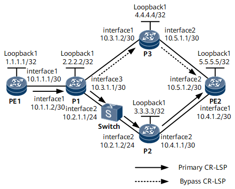
On the MPLS network shown in Figure 1, a Layer 2 device (switch) is deployed on a link between P1 and P2. A primary MPLS TE tunnel between PE1 and PE2 is established over a path PE1 -> P1 -> switch -> P2 -> PE2. A TE FRR bypass tunnel between P1 and PE2 is established over the path P1 -> P3 -> PE2. P1 functions as the point of local repair (PLR), and PE2 functions as the merge point (MP).
If the link between the switch and P2 fails, P1 keeps sending the switch RSVP messages (including Hello messages) destined for P2 and detects the fault only after P1 fails to receive replies to RSVP Hello messages sent to P2.
The timeout period of RSVP neighbor relationships is three times as long as the interval between Hello message transmissions. After the timeout period elapses, P1 declares its neighbor Down, which is seconds slower than it does when there is no Layer 2 device. The fault detection latency causes a large number of packets to be dropped. To minimize traffic loss, BFD can be configured to rapidly detect the fault in the link between P2 and the switch. After a BFD session detects the fault, it advertises the fault to trigger TE FRR switching.
Configuration Roadmap
The configuration roadmap is as follows:
Configure an IP address for each interface and enable IGP on each LSR so that LSRs can communicate. Enable IGP GR to support RSVP GR.
Configure the MPLS network and basic MPLS TE functions.
Configure explicit paths for the primary and bypass tunnels.
Create the primary tunnel interface and enable TE FRR on PE1. Configure the bypass tunnel on P1.
Configure BFD for RSVP on P1 and P2.
Data Preparation
To complete the configuration, you need the following data:
IGP protocol and parameters
MPLS LSR IDs
Bandwidth attributes of the outbound interfaces of links along the tunnel
Primary tunnel interface number and explicit path
Bypass tunnel interface number and explicit path
Physical interfaces to be protected by the bypass tunnel
Minimum intervals at which BFD packets are sent and received
Local BFD detection multiplier
Procedure
- Assign an IP address to each interface.
Assign an IP address to each interface according to Figure 1, create loopback interfaces on LSRs, and configure the loopback interface addresses as MPLS LSR IDs. For configuration details, see Configuration Files in this section.
- Configure the switch.
Configure the switch so that P1 and P2 can communicate. For configuration details, see Configuration Files in this section.
- Configure an IGP.
Configure OSPF or IS-IS on each LSR so that LSRs can communicate. In this example, IS-IS is used. For configuration details, see Configuration Files in this section.
- Configure basic MPLS functions.
Configure the LSR ID and enable MPLS in the system and interface views on each LSR. For configuration details, see Configuration Files in this section.
- Configure basic MPLS TE functions.
Enable MPLS TE and MPLS RSVP-TE in the MPLS and interface views on each LSR. For configuration details, see Configuration Files in this section.
- Configure IS-IS TE and CSPF.
Enable IS-IS TE on each node and configure CSPF on PE1 and PE2. For configuration details, see Configuration Files in this section.
- Configure the primary tunnel.
# Specify an explicit path for the primary tunnel on PE1.
<PE1> system-view
[~PE1] explicit-path tope2
[*PE1-explicit-path-tope2] next hop 10.1.1.2
[*PE1-explicit-path-tope2] next hop 10.2.1.2
[*PE1-explicit-path-tope2] next hop 10.4.1.2
[*PE1-explicit-path-tope2] next hop 5.5.5.5
[*PE1-explicit-path-tope2] commit
[~PE1-explicit-path-tope2] quit
# Create a tunnel interface on PE1, specify an explicit path, and enable TE FRR.
[~PE1] interface Tunnel 10
[*PE1-Tunnel10] ip address unnumbered interface loopback 1
[*PE1-Tunnel10] tunnel-protocol mpls te
[*PE1-Tunnel10] destination 5.5.5.5
[*PE1-Tunnel10] mpls te tunnel-id 100
[*PE1-Tunnel10] mpls te path explicit-path tope2
[*PE1-Tunnel10] mpls te fast-reroute
[*PE1-Tunnel10] commit
[~PE1-Tunnel10] quit
# Run the display mpls te tunnel-interface tunnel command on PE1. The status of Tunnel 10 on PE1 is Up.
- Configure the bypass tunnel.
# Specify the explicit path for the bypass tunnel on P1.
<P1> system-view
[~P1] explicit-path tope2
[*P1-explicit-path-tope2] next hop 10.3.1.2
[*P1-explicit-path-tope2] next hop 10.5.1.2
[*P1-explicit-path-tope2] next hop 5.5.5.5
[*P1-explicit-path-tope2] commit
[~P1-explicit-path-tope2] quit
# Configure a bypass tunnel interface and specify an explicit path for the bypass tunnel on P1. Specify the physical interface to be protected by the bypass tunnel.
[~P1] interface Tunnel 30
[*P1-Tunnel30] ip address unnumbered interface loopback 1
[*P1-Tunnel30] tunnel-protocol mpls te
[*P1-Tunnel30] destination 5.5.5.5
[*P1-Tunnel30] mpls te tunnel-id 300
[*P1-Tunnel30] mpls te path explicit-path tope2
[*P1-Tunnel30] mpls te bypass-tunnel
[*P1-Tunnel30] mpls te protected-interface gigabitethernet 0/1/8
[*P1-Tunnel30] commit
[~P1-Tunnel30] quit
- Configure BFD for RSVP.
# Enable BFD for RSVP on GE 0/1/8 on P1 and P2. Set the minimum intervals at which BFD packets are sent and received, and the local BFD detection multiplier.
# Configure P1.
[~P1] bfd
[*P1-bfd] quit
[*P1] interface gigabitethernet 0/1/8
[*P1-GigabitEthernet0/1/8] mpls rsvp-te bfd enable
[*P1-GigabitEthernet0/1/8] mpls rsvp-te bfd min-tx-interval 100 min-rx-interval 100 detect-multiplier 3
[*P1-GigabitEthernet0/1/8] commit
[~P1-GigabitEthernet0/1/8] quit
# Configure P2.
[~P2] bfd
[*P2-bfd] quit
[*P2] interface gigabitethernet 0/1/8
[*P2-GigabitEthernet0/1/8] mpls rsvp-te bfd enable
[*P2-GigabitEthernet0/1/8] mpls rsvp-te bfd min-tx-interval 100 min-rx-interval 100 detect-multiplier 3
[*P2-GigabitEthernet0/1/8] commit
[~P2-GigabitEthernet0/1/8] quit
- Verify the configuration.# After the configuration is complete, run the display mpls rsvp-te bfd session { all | interface interface-type interface-number | peer ip-address } [ verbose ] command on P1 and P2. The BFD session status is up. The following example uses the configuration on P1.
<P1> display mpls rsvp-te bfd session all
Total Nbrs/Rsvp triggered sessions : 3/1
-------------------------------------------------------------------------------
Local      Remote     Local           Peer            Interface       Session
Discr      Discr      Addr            Addr            Name            State
-------------------------------------------------------------------------------
16385      16385      10.2.1.1        10.2.1.2        GE0/1/8         UP
Configuration Files

The switch configuration file is not provided here.
PE1 configuration file
#
sysname PE1
#
mpls lsr-id 1.1.1.1
#
mpls
 mpls te
 mpls rsvp-te
 mpls rsvp-te hello
 mpls te cspf
#
explicit-path tope2
 next hop 10.1.1.2
 next hop 10.2.1.2
 next hop 10.4.1.2
 next hop 5.5.5.5
#
isis 1
 is-level level-2
 cost-style wide
 network-entity 86.4501.0010.0100.1001.00
 traffic-eng level-2
#
interface GigabitEthernet0/1/0
 undo shutdown
 ip address 10.1.1.1 255.255.255.252
 isis enable 1
 mpls
 mpls te
 mpls rsvp-te
 mpls rsvp-te hello
#
interface LoopBack1
 ip address 1.1.1.1 255.255.255.255
 isis enable 1
#
interface Tunnel10
 ip address unnumbered interface LoopBack1
 tunnel-protocol mpls te
 destination 5.5.5.5
 mpls te record-route label
 mpls te fast-reroute
 mpls te tunnel-id 100
 mpls te path explicit-path tope2
#
return
P1 configuration file
#
sysname P1
#
bfd
#
mpls lsr-id 2.2.2.2
#
mpls
 mpls te
 mpls rsvp-te
 mpls rsvp-te bfd all-interfaces enable
 mpls rsvp-te bfd all-interfaces min-tx-interval 100 min-rx-interval 100 detect-multiplier 4
 mpls rsvp-te hello
 mpls te cspf
#
explicit-path tope2
 next hop 10.3.1.2
 next hop 10.5.1.2
 next hop 5.5.5.5
#
isis 1
 is-level level-2
 cost-style wide
 network-entity 86.4501.0020.0200.2002.00
 traffic-eng level-2
#
interface GigabitEthernet0/1/16
 undo shutdown
#
interface GigabitEthernet0/1/0
 undo shutdown
 ip address 10.1.1.2 255.255.255.252
 isis enable 1
 mpls
 mpls te
 mpls rsvp-te
 mpls rsvp-te hello
#
interface GigabitEthernet0/1/8
 undo shutdown
 ip address 10.2.1.1 255.255.255.252
 isis enable 1
 mpls
 mpls te
 mpls rsvp-te
 mpls rsvp-te bfd enable
 mpls rsvp-te bfd min-tx-interval 100 min-rx-interval 100
 mpls rsvp-te hello
#
interface GigabitEthernet0/1/16
 undo shutdown
 ip address 10.3.1.1 255.255.255.252
 isis enable 1
 mpls
 mpls te
 mpls rsvp-te
 mpls rsvp-te hello
#
interface LoopBack1
 ip address 2.2.2.2 255.255.255.255
 isis enable 1
#
interface Tunnel30
 ip address unnumbered interface LoopBack1
 tunnel-protocol mpls te
 destination 5.5.5.5
 mpls te record-route
 mpls te tunnel-id 300
 mpls te path explicit-path tope2
 mpls te bypass-tunnel
 mpls te protected-interface Gigabitethernet 0/1/8
#
return
P2 configuration file
#
sysname P2
#
bfd
#
mpls lsr-id 3.3.3.3
#
mpls
 mpls te
 mpls rsvp-te
 mpls rsvp-te hello
 mpls te cspf
#
isis 1
 is-level level-2
 cost-style wide
 network-entity 86.4501.0030.0300.3003.00
 traffic-eng level-2
#
interface GigabitEthernet0/1/0
 undo shutdown
 ip address 10.4.1.1 255.255.255.252
 isis enable 1
 mpls
 mpls te
 mpls rsvp-te
 mpls rsvp-te hello
#
interface GigabitEthernet0/1/8
 undo shutdown
 ip address 10.2.1.2 255.255.255.252
 isis enable 1
 mpls
 mpls te
 mpls rsvp-te
 mpls rsvp-te bfd enable
 mpls rsvp-te bfd min-tx-interval 100 min-rx-interval 100
 mpls rsvp-te hello
#
interface LoopBack1
 ip address 3.3.3.3 255.255.255.255
 isis enable 1
#
return
P3 configuration file
#
sysname P3
#
mpls lsr-id 4.4.4.4
#
mpls
 mpls te
 mpls rsvp-te
 mpls rsvp-te hello
 mpls te cspf
#
isis 1
 is-level level-2
 cost-style wide
 network-entity 86.4501.0040.0400.4004.00
 traffic-eng level-2
#
interface GigabitEthernet0/1/0
 undo shutdown
 ip address 10.3.1.2 255.255.255.252
 isis enable 1
 mpls
 mpls te
 mpls rsvp-te
 mpls rsvp-te hello
#
interface GigabitEthernet0/1/8
 undo shutdown
 ip address 10.5.1.1 255.255.255.252
 isis enable 1
 mpls
 mpls te
 mpls rsvp-te
 mpls rsvp-te hello
#
interface LoopBack1
 ip address 4.4.4.4 255.255.255.255
 isis enable 1
#
return
PE2 configuration file
#
sysname PE2
#
mpls lsr-id 5.5.5.5
#
mpls
 mpls te
 mpls rsvp-te
 mpls rsvp-te hello
 mpls te cspf
#
isis 1
 is-level level-2
 cost-style wide
 network-entity 86.4501.0050.0500.5005.00
 traffic-eng level-2
#
interface GigabitEthernet0/1/0
 undo shutdown
 ip address 10.4.1.2 255.255.255.252
 isis enable 1
 mpls
 mpls te
 mpls rsvp-te
 mpls rsvp-te hello
#
interface GigabitEthernet0/1/8
 undo shutdown
 ip address 10.5.1.2 255.255.255.252
 isis enable 1
 mpls
 mpls te
 mpls rsvp-te
 mpls rsvp-te hello
#
interface LoopBack1
 ip address 5.5.5.5 255.255.255.255
 isis enable 1
#
return